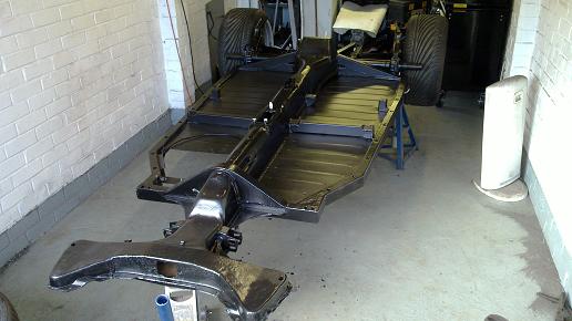
Chassis and Brakes
|
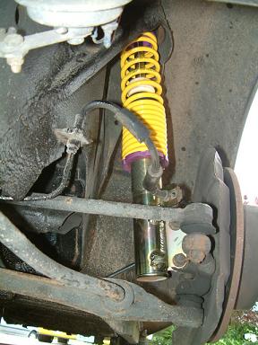
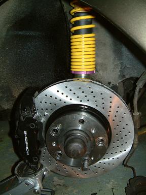
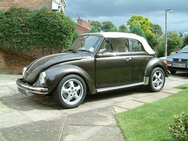
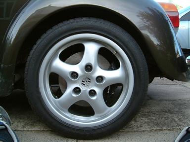
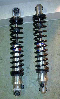
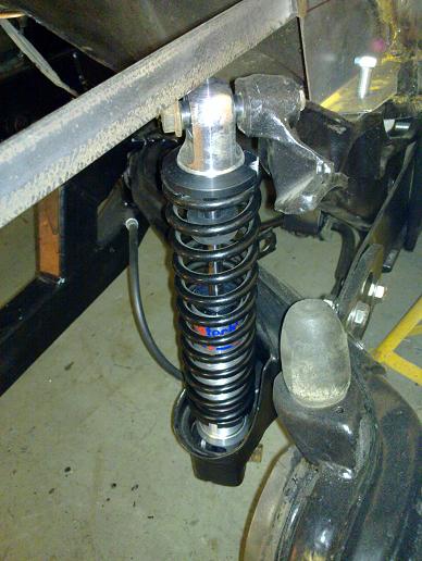
Here are the Kerscher struts fitted. I'm not going too low as the Subaru sump will need some help getting over speed bumps! They feature adjustable Koni insets and progressive Eibach springs. |
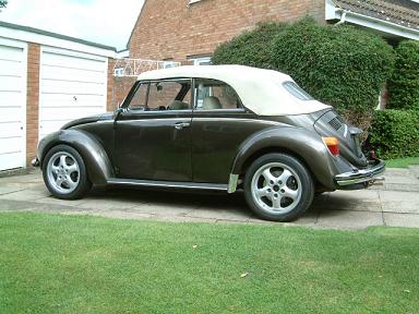
The rear will drop a bit with the weight of the Subaru engine. |
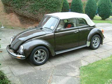
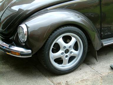
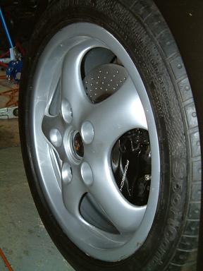
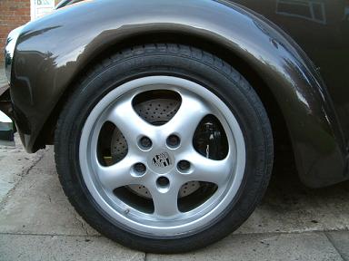
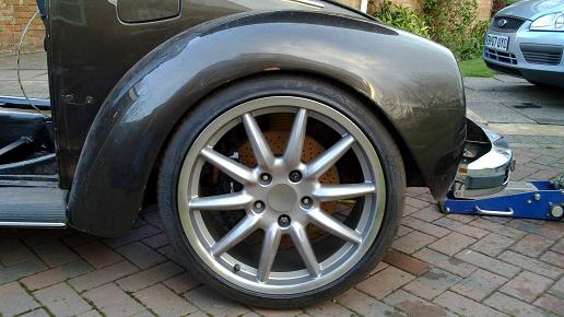
Test fitting one of the Cup wheels reveals it will be a very snug fit but do-able under standard width wings. |
|
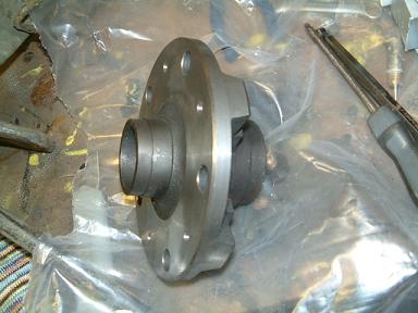
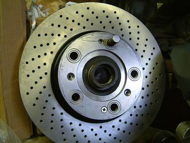
I had to drill and tap for the disc retaining screw as none of the others matched up. |
|
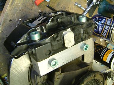
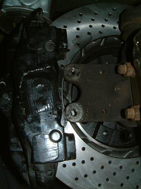
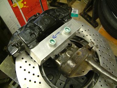
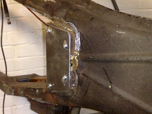
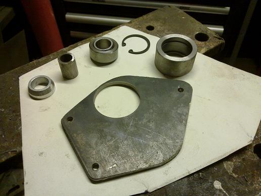
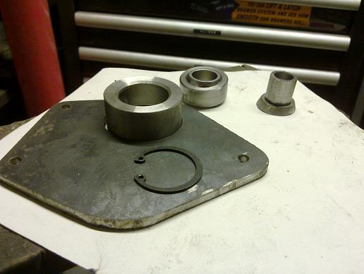
Here's the rear caliper adapter. I built up the caliper with pads, positioned it on the disc (1986 944 turbo) and then measured what was required from the adapter. The adapter is made from T6 aluminium that I got a meter length of on ebay. |
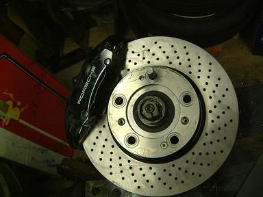
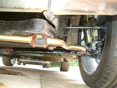
Rear all assembled! Just need to reverse the link pipe and bleed nipples as they need swapping over side to side due to the different piston sizes in the calipers. |
|
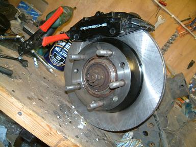
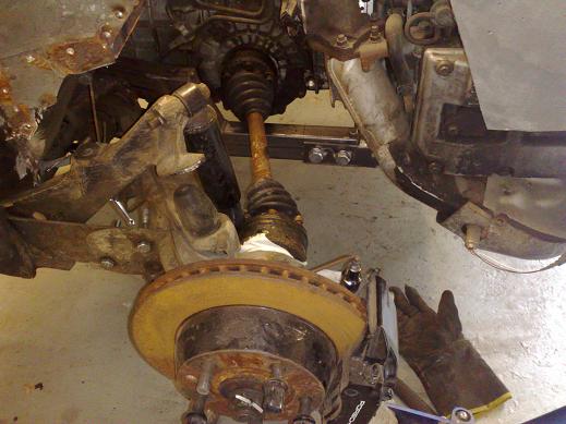
Calipers and discs trial fitted up, the disc went on fine but not so lucky for the caliper! |
The original spindle lugs don't let the caliper go on far enough... |
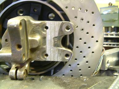
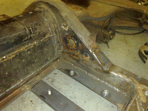
Here's the finished assembly from the front |
|
and the back! This was quite a simple way of doing things in the end. The new holes in the spindle have been tapped for an M12x1.5 so all the bolts are the same. |
|
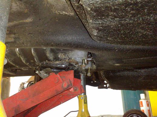
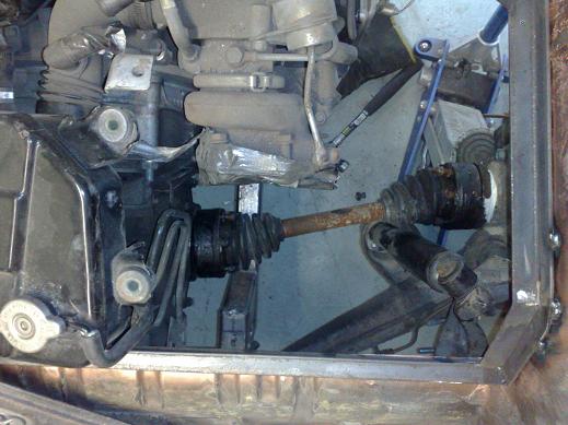
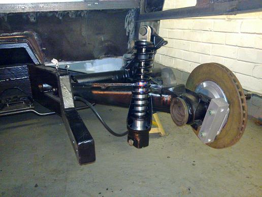
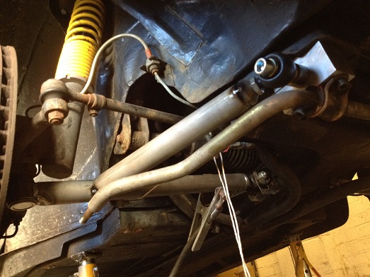
| Pic of front suspension after the front suspension was refurbished with new urethane bushes and tie rod.
|
|
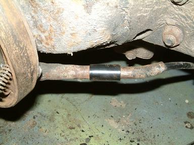
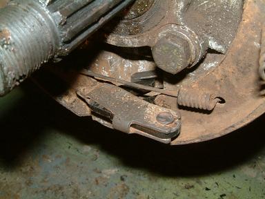
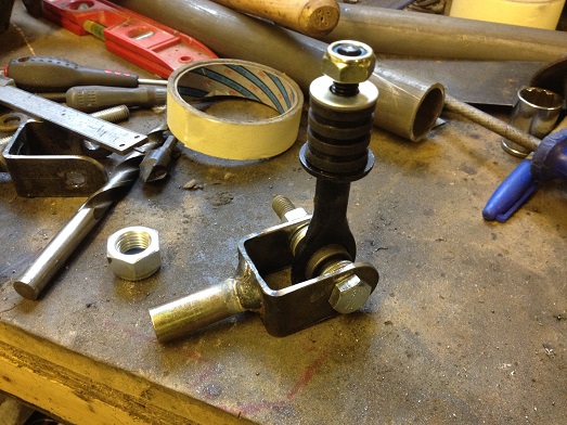
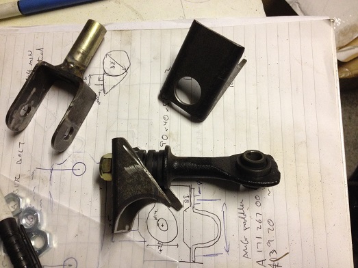
Rear beetle handbrake cable was adapted using a kit form Vdubcustoms in Canada. This sleeve adapts the stock cable to the 944 parts. |
and this new 'swan neck' lets the stock beetle cable end mate up with the 944 handbrake internals. |
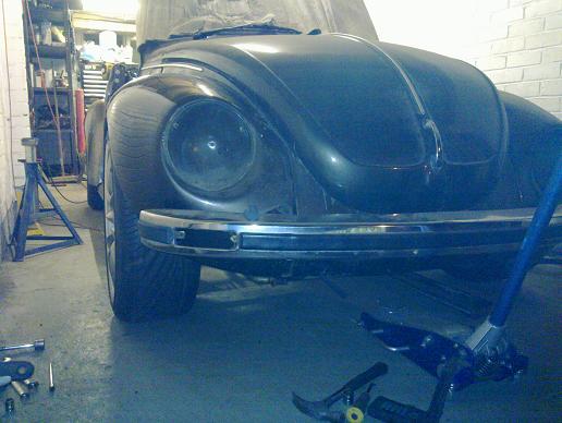
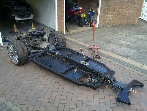
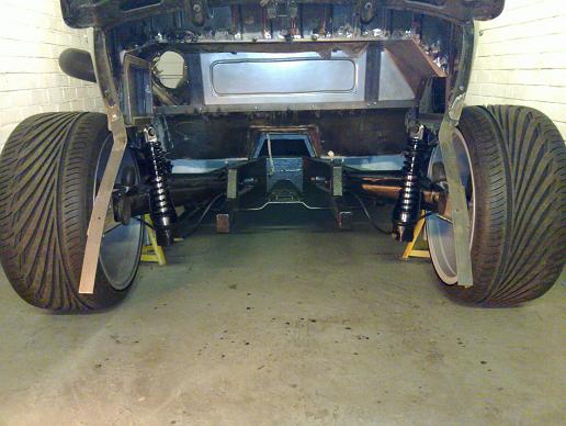
Bug is back on 4 wheels! |
Just need to make some longer rigid brake lines and then purge with new brake fluid. I think the rear will drop to a nice height with weight of the Subaru engine.. |
|
Took it for a test drive and the performance is amazing without needing too much pedal effort on the stock master cylinder... |
Fronts |
|
Rears |
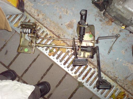
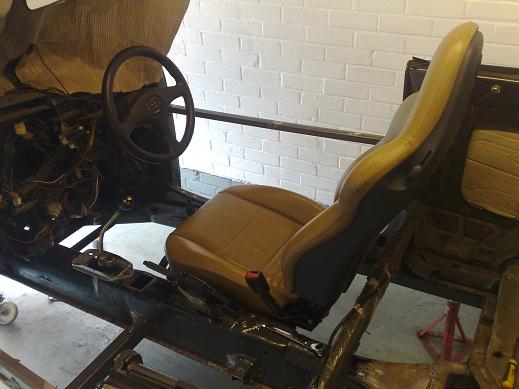
Pedals from a 1989 911, I will at least use the hydraulic clutch, if not the complete assembly |
|
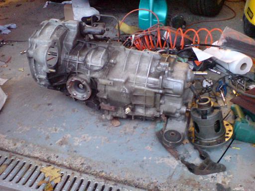
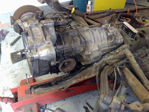
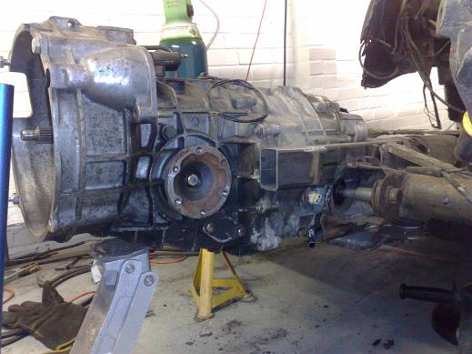
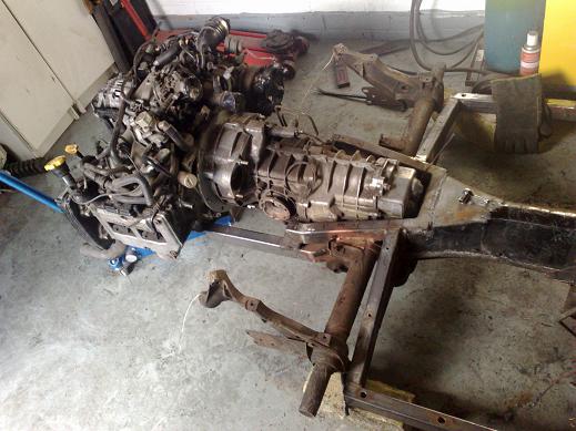
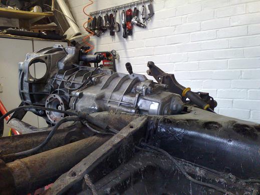
Gearbox from the same car, a G50/00 with only 20k miles on it! |
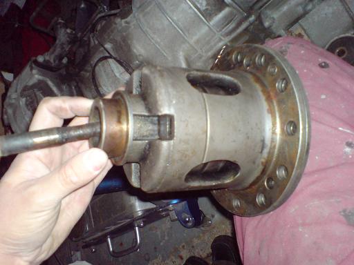
and a clutch type LSD, I need to do some research into this to find out exactly what it is! |
|
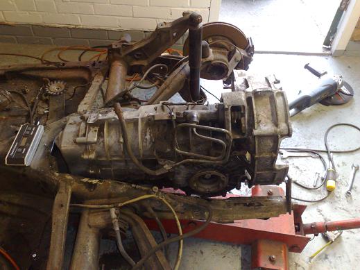
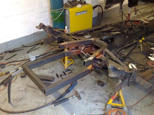
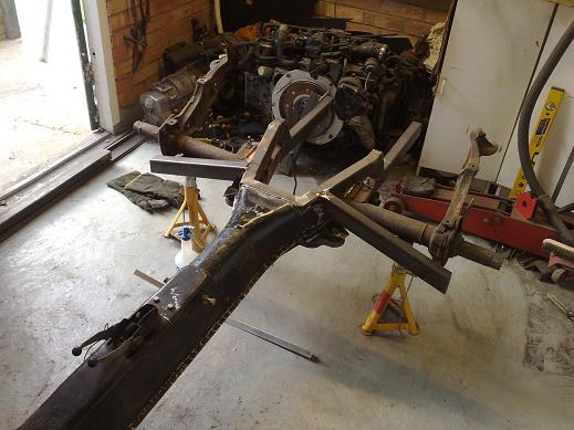
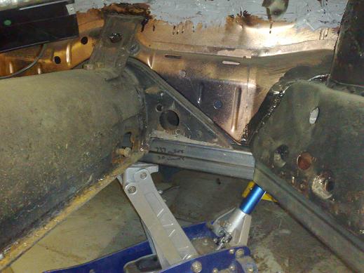
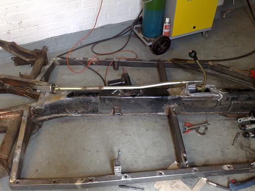
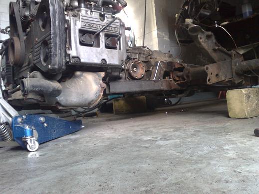
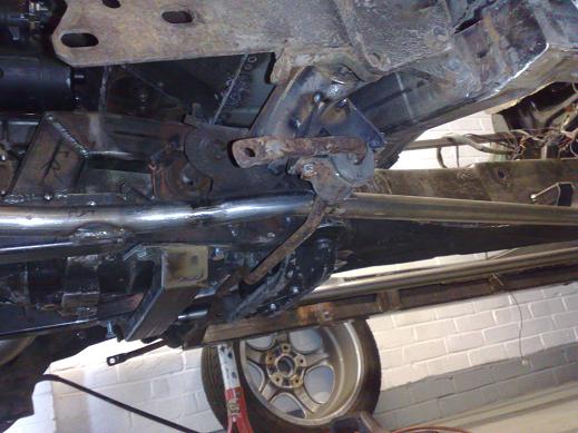
Trans mocked up in roughly the right position under the chassis. It will be about another inch further forwards than the AT trans I had fitted temporarily and an inch higher. CV angles don't look too bad... |
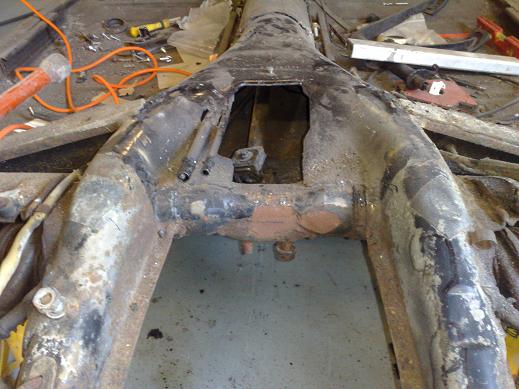
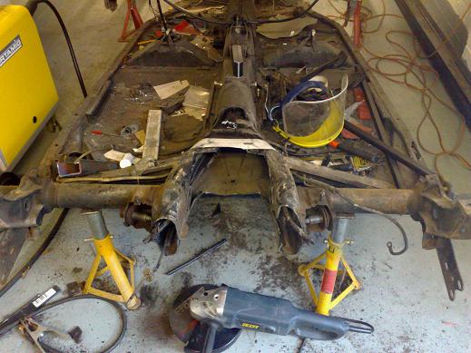
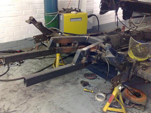
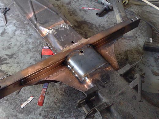
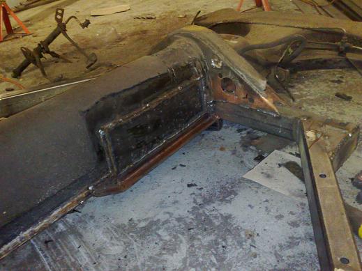
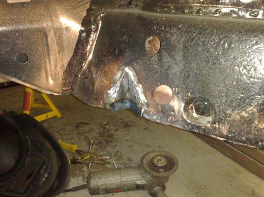
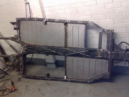
Next phase is to cut through the torsion bar housing, I may replace the framehorns with a slightly lower tube at the bottom and a semi-spaceframe arrangement over the top, similar to a bus. |
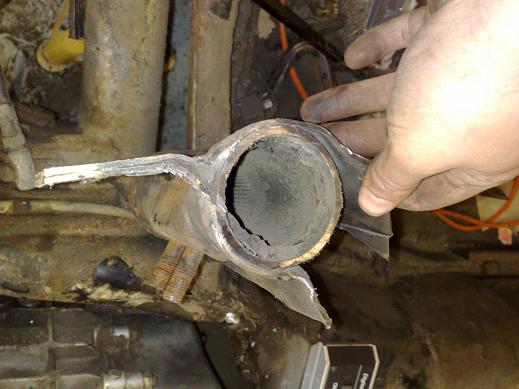
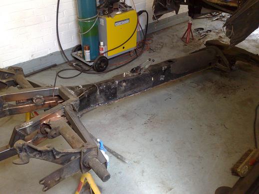
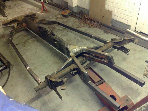
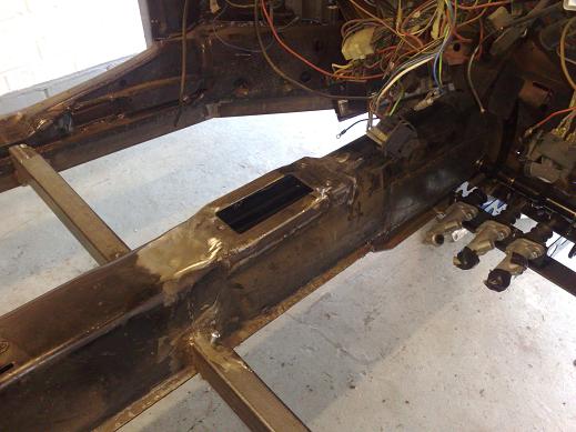
Central section cut out to enable forward shift of the transmission. A 2mm cutting disc in my 9" angle grinder did the job, but unfortunately also cut through the left handbrake cable tube! |
|
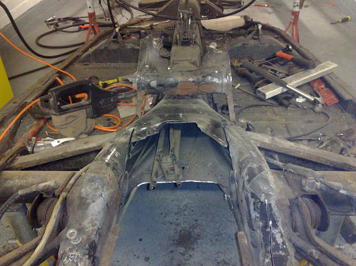
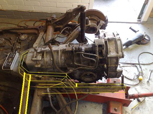
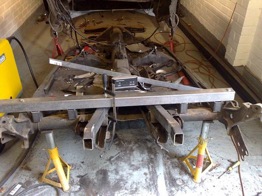
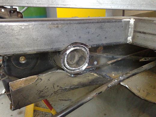
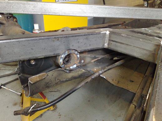
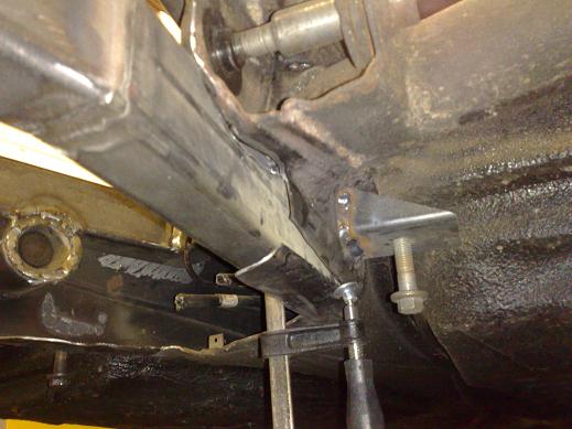
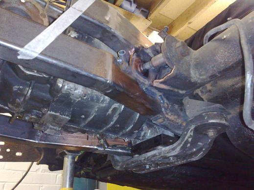
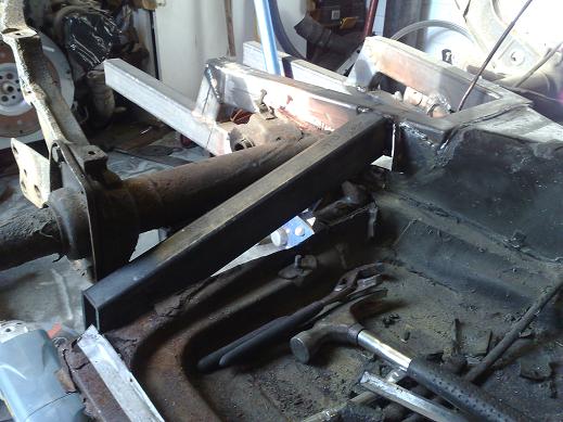
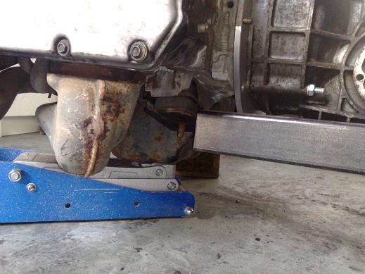
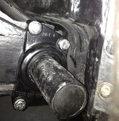
You can see here how I have set the position of the rear of the trans using threaded bars. Quite a lot of clearancing of the right framehorn was needed |
The left framehorn hardly needed touching at all |
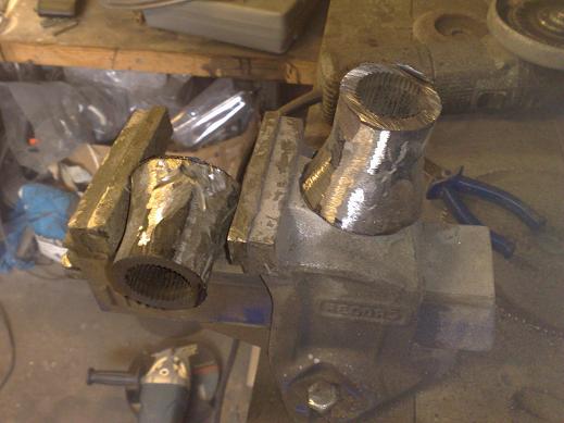
The centre section will have the splined section removed and welded in to the torsion tube further out to allow the use of swing axle torsion bars. |
 |
I will probably use the stock front transmission mount spaced away from the trans by about an inch |
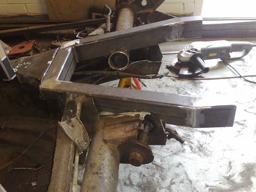
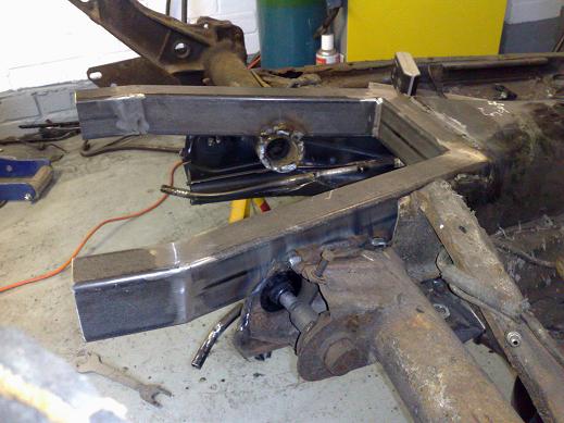
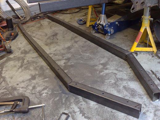
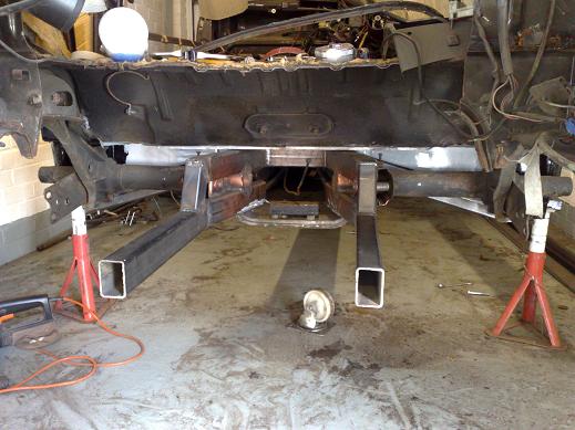
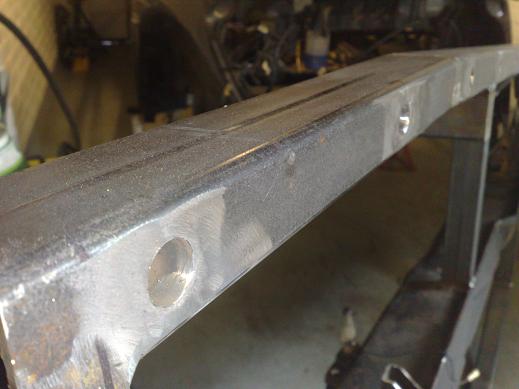
My initial idea for new framehorns, this will be made out of 40x60x3mm steel tube and will extend back to meet the stock Subaru engine mounts. The loop around the front of the trans will go some way to getting the strength back in across the section that I cut out. |
Trans refitted to check bracket location. |
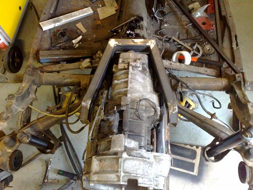
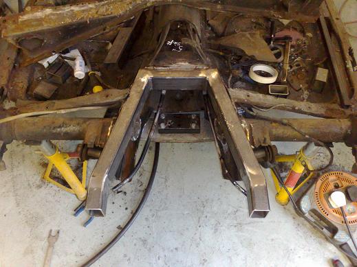
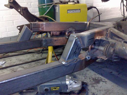
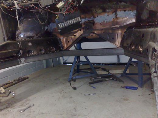
New framehorn shape is defined while the transmission is still in the car, this is the top 'rail' section, I wanted to make sure there was clearance all around the trans... |
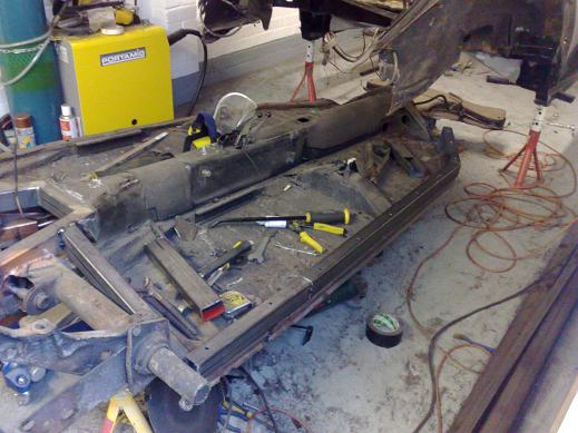
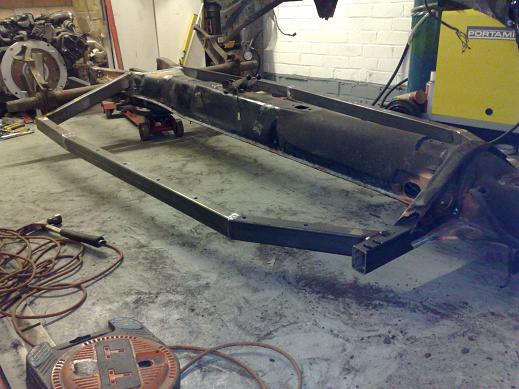
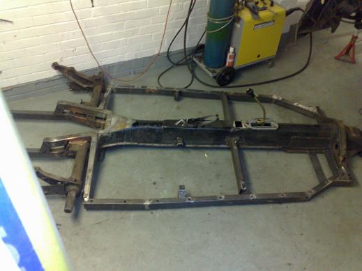
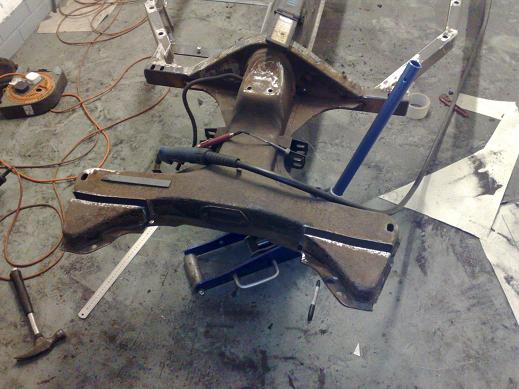
framehorns finally completely cut off, no going back now!!! |
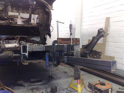
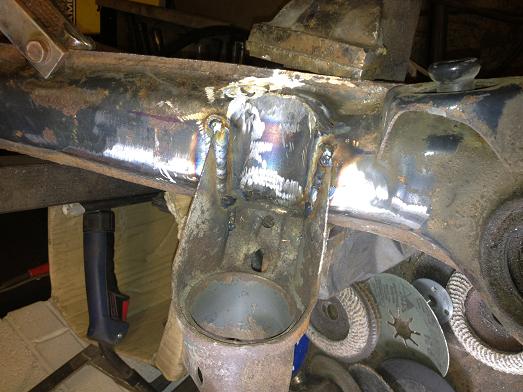
After the centre was cut out the outer sections of the torsion tube were not properly aligned, this makeshift jig brought it all back straight before the top framehorn tube was welded in. |
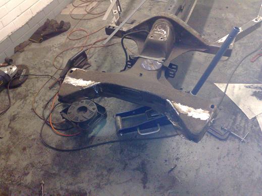
This is the amount of clearancing that was required to go around the torsion tube and inner suspension brackets |
Loosely fitted in place... |
The old centre splined section was stripped down and cleaned up, then cut in two before being trimmed to fit and generously chamfered to get a good weld |
ready for welding... |
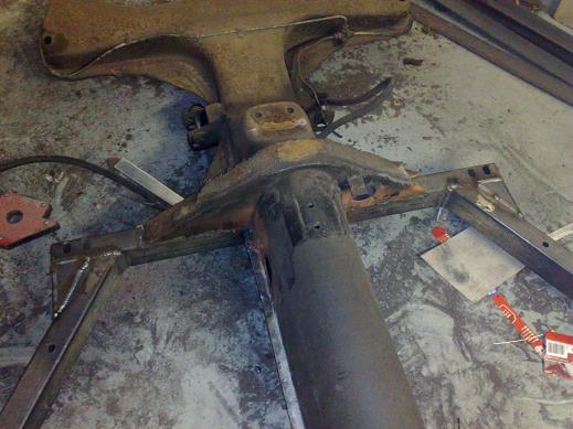
Welded in... |
Lots of measuring with the digital level to make sure it was all square was done before fully welding it in place |
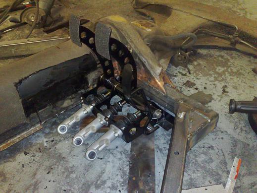
Repaired handbrake tubes aren't strong enough so I will remake them, here the front trans mount is loosely bolted back in place so I can work out how to do the bottom tubes. |
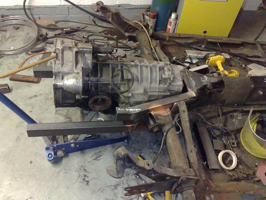
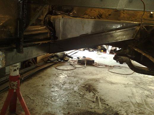
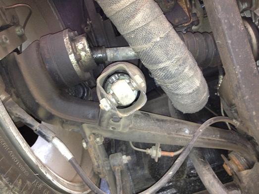
Just a quick check to see how the trans fits, here you can see how much more volume there is on the right hand side of the gearbox. |
It may seem minor, but I didn't want to sacrifice the reverse light switch, you can see it just by the inner IRS bracket in this picture and it will stay accessible between the upper and lower tubes. I did some measuring to where the subaru engine bushings will end up and they will lign up about perfectly with the end of the bottom tube! |
I had to cut down the radius of the bottom of the original framehorn so it would fit nicely. |
Just a quick mock-up while clearancing the lower tube for the torsion tube and IRS bracket. Note it is over-long and I will trim it to length when the engine is fitted to suit the engine mounts. |
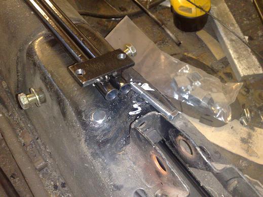
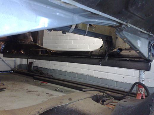
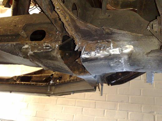
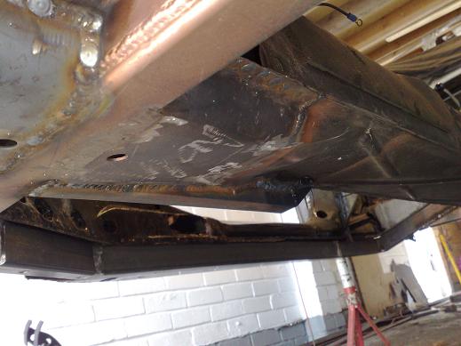
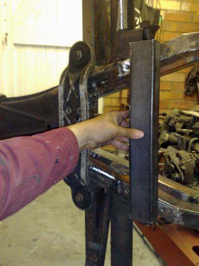
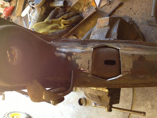
Here's how I have replaced the handbrake cable guide tubes, it bolts up underneath the top of tunnel using bolts through the top into a threaded plate. |
Seam welded all around, you can also see the handbrake tube welded in place |
|
|
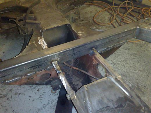
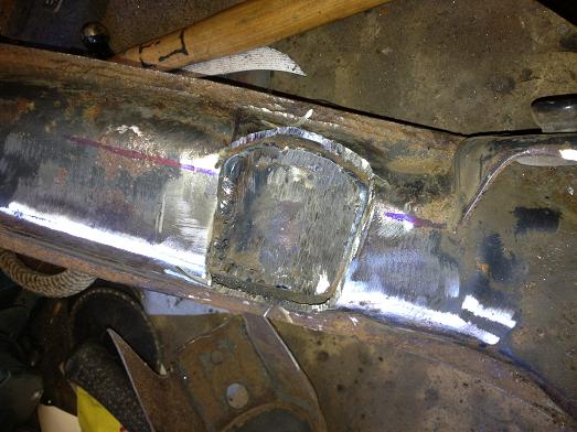
Test fitting the trans to measure where the joining sections can go, making sure there's clearance to the CV flanges |
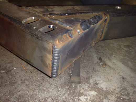
First joint welded in. |
Framehorns done!!!! |
|
Side tubes made on the old floors to get the correct profile and bolt positions |
Trial fitted on the body (both sides) |
Then a second one made up. |
|
Both rear sections now tacked in ready for trial fit to the body |
Both side rails bolted in place, I've also temporarily bolted in the front tube, this will become the bottom section of the napolean's hat on the chassis... |
Rear sections required a bit more fettling to line up nicely, they were then removed and tapped for the body bolts... |
|
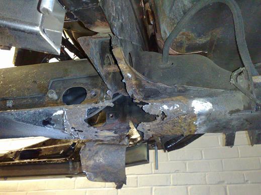
Bottom of framehead was a disaster zone! Pidgeon shit welding covered by filler.... twice!!! |
All came off... |
Here's how the bottom section now sits, nearly there! Next step is to weld it all up then drop the chassis from hte body and then I'll fix the bottom of the framehead. |
|
I'll be reworking the napolean's hat for the hydraulic clutch master cylinder and also be adding crossmembers for seat mounts. |
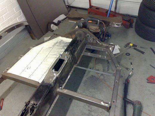
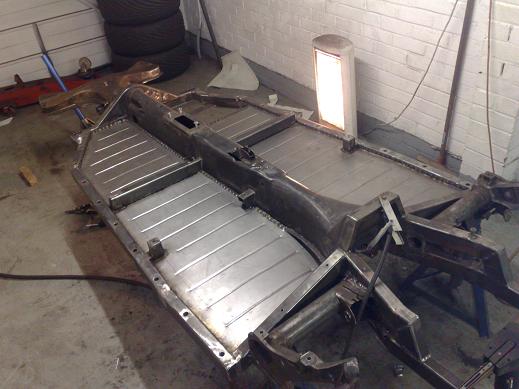
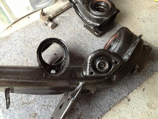
Chassis flipped upside down to finish off chassis welding. Bottom of bulkhead area with all rust cut out and local repairs |
New repair panels fabricated in 2mm steel and welded in place, not forgetting some drain holes so hopefully prevent all that rust re-appearing in the future! |
I decided to re-make the front transmission cradle mounts and tie them into the rear frame, this is much neater and stronger. |
Both sides done... |
Gussets added to the front section of the chassis. Much tidier and will add a decent amount of strength in torsion. |
Both sides done... |
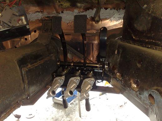
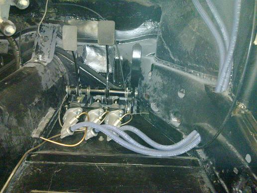
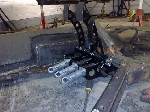
Reverse mount hydraulic pedal assembly from OBP. I'll sink the floor flush to the bottom of the chassis in this area and hopefully move the pedals a bit more central to the footwell. |
Floor mounting flange now remade to drop the floor, the centre tunnel side slightly narrowed/smoothed for a bit more room. |
 |
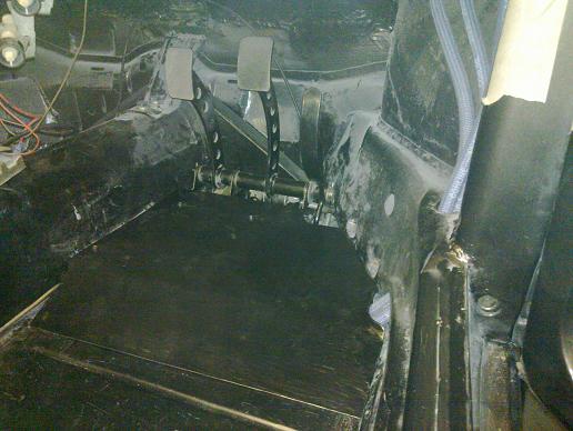
Here you can see how the dropped floor is blended in to the tunnel. |
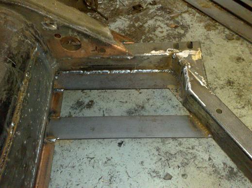
After some trimming to make more room so I can move the pedals over more centrally. I've welded in two 5mm thick strips to mount the pedal box on to. The throttle cable will come through the front tube back to the pedal and this makes more space for that too. |
You can just about see that the throttle pedal pivot comes very close to the footwell strengthener panel, I'll notch this out to give more clearance and enable easier assembly. |
Strengthener panel now notched to give more clearance to the throttle pedal shaft. |
Getting there! |
|
Welding captive nuts into the bottom of the new framehorns for a removable bottom tube. I think the chassis will be a fair bit stronger than stock even though I have cut the central section out... |
Fine-tuning the shifter position |
|
Pic of shift rod before smoothing/painting so you can see the extra 120mm section that needed adding |
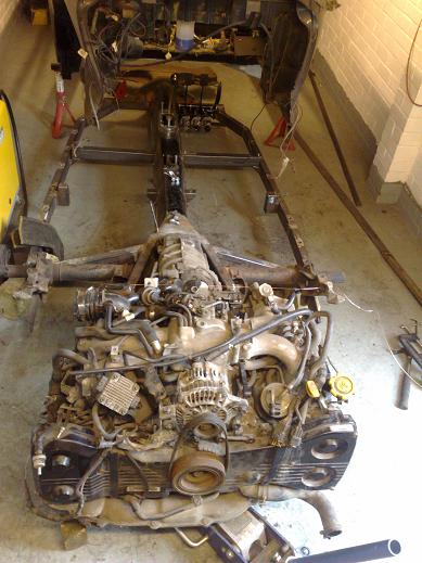
Engine finally in the chassis!
|
Looking almost finished from this angle... |
Transmission sits nicely up and out of the way, this is probably not far off the final ride height. |
Just have to make the engine mounts and figure out a neat way of attaching them to the end of the framehorn |
Pic of tunnel modified for the 911 shifter |
Removable brace now made, anti-roll bar will sit between it and the front trans mount |
Chassis modified with a steel tube hoop over the nose of the gearbox and a transmission tunnel built in to the body, I used the edge flange from the old crossmembers to preserve a factory appearance and also left a small gap for the body gasket. |
Access to the shifter coupling was very fiddly before, much easier now with this removable section. |
|
|
Napolean's hat repaired and redundant holes filled |
|
Angle is about 12 degrees. Clearance to the damper isn't great, I may modify the trailing arm to get a bit more clearance so I can use coil-overs later on. |
Brackets modified from the old 944 rear end I bought and welded on to the bug's torsion bar housing, it fits nicely between the trans front mount and the framehorn brace. |
To gain more caster, the simplest way was to move the anti-roll bar mountings forwards, I trialled a 20mm spacer and that worked perfectly so that is how much I have extended the chassis by... I believe adjustable anti-roll bars are available in some parts of the world... |
|
All welded up and ground smooth |
Chassis closed up around the front of the trans to give some extra strength. |
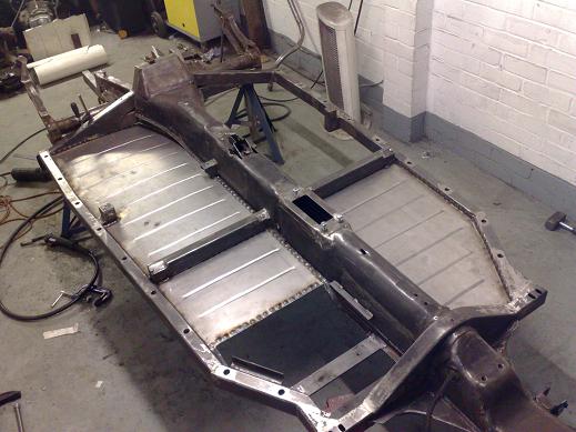
Beadroller paying for itself now! Rear floor section is flat (apart from the ribs), the dropped floor section by the pedals will be a removable aluminium panel so won't be done until after paint. |
 |
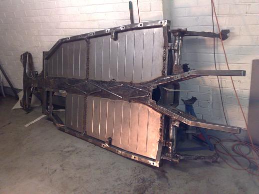 |
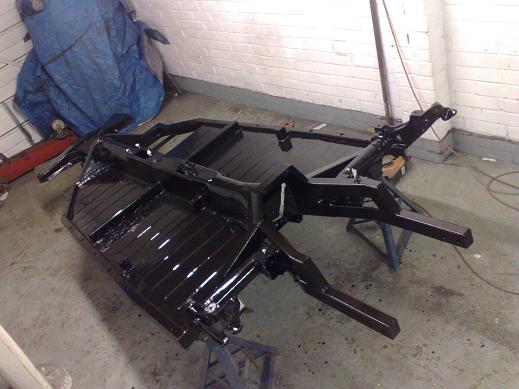
Floors in, paint next! |
First coat of paint! I'm using epoxy mastic 121 this time as I've heard very good reports. POR-15 can be good but is a real pain with so many prep stages required for it to work well. |
Trailing arms and spring plates also stripped and painted. I'll be replacing the stubaxles with G50 sized ones... |
 |
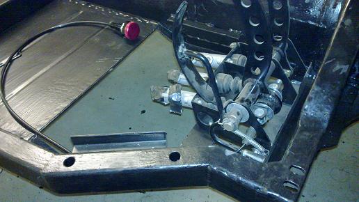
Not much space for the brake bias adjuster cable, so I routed it inside the chassis tube. The knob will probably be fitted on the A post just below the base of the dash. |
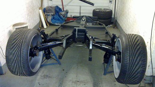
Chassis mod has worked out great, wheel now nicely centred. |
Quick image of how it looks with the body on, now time to get cracking on the body! |
I went for the biggest bushes pro-tech had and didn't need any spacers at the top mounting, small ones either side at the lower end. |
|
I held a G50 911 axle in position and luckily it looks like there will be enough clearance to the spring. Normally this wouldn't be an issue but with the trans moved forwards it was something I needed to check... |
 |
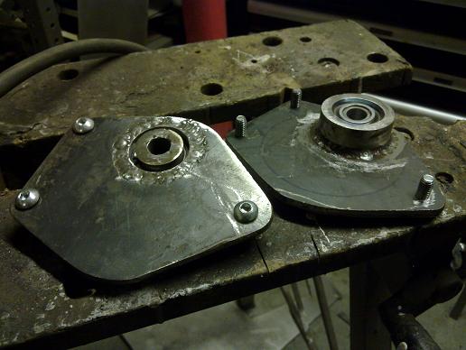
Decided to make up my own spherical top strut mounts. |
|
|
All welded up |
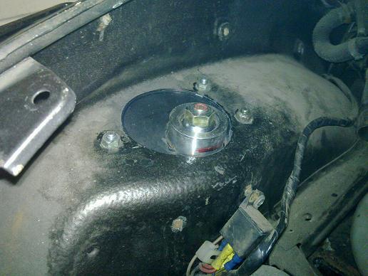
Trial mounted before fully welding. |
Suspension arm also shortened by 15mm so I could ge tthe bigger wheels nicely fitted under the stock front wings. Turning circle will be increased a bit but it was very good to start with so shouldn't be too bad. |
All mounted up and a nice fitment with 1,5 degrees of camber... |
I made up a couple of aluminium plates to stop the torsion bars sliding inside, also a small bracket for the 2 new fuel pipes (5/16" kinifer) which ended up clashing with the body so I'll have to redo that! |
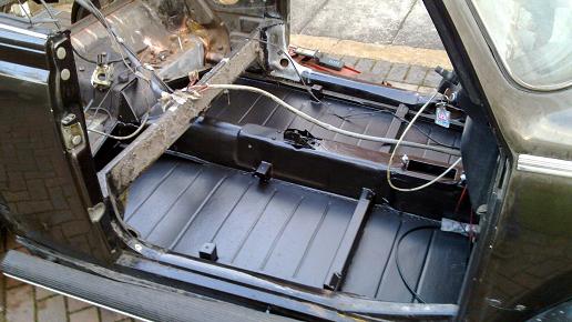
You can just make out the chargecooler pipes coming out through a new plate at the front of the chassis, I also ran new front and rear brake lines. Instead of the usual cheap rubber body gaskets, I bought a long length of foam gasket and made my own VW style one, didn't take too long, hole punching it as I went to line up with the body mount holes and then glued any ends together with sikaflex. |
Brake reservoir (911) fitted under bonnet and supply lines pipes down to the master cylinders. The system is now all bled and seems to work OK with no leaks... |
New false floor... |
I modified one of the front bumper brackets to take a removable towing eye. |
|
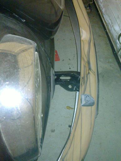
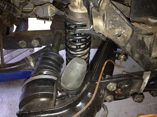
After the trip to Spa, the race style compact boots finally gave up with dealing with the CV angle. They are mainly designed for race cars and are basically an inverted cone with little give so not surprising really. They were necessary to clear the coil-over springs. This picture is from underneath with the car on a 2 post lift and the suspension at full rebound so definitely not the worst position, the damper swings closer to the axle at ride height. |
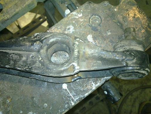
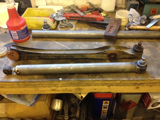
The long term fix was always to relocate the coil-over. I had a spare pair of trailing arms from a 944, these are identical to the beetle ones with the exception of some internal strengthening. |
I made up new curved section to take a scallop out of the arm and also reweld the lower damper mount about 15mm further forwards. |
All back together ready for clean up and paint. |
Better view showing the additional clearance made. |
As before this is with the suspension in full droop but now with a nice big silicone off road style CV boot that is designed for much more angularity than I will subject it to. At ride height I can get a finger between the spring and boot so clearance is no longer an issue. While I was at it I also fitted the 944 spring plates with the built in capability of a camber bolt anti-roll bar fitting to set the camber, it is also designed to take a toe adjustment tool. I had to lose the ride height adjustment due to clearance problems with the wheel but wiht the adjustable coil-overs this really isnt' an issue for me... |
After seeing a few other 1303s modified to have a proper lower A arm for the strut I decided to finally have a go myself. I wanted to do it as a completely bolt on swap. Part of this change is to de-couple the stock anti-roll bar from the geometry so this will be spaced down underneath the A arm. I've seen people put it above but my radiator is in the way and I have plenty of ground clearance. The inner spherical joint will be M10 and the forward tension link section will be M14, I will also be using sealed boots to keep them weather tight. At the spindle I'm using the original design ball joint. Some people re-position the lower axis as they run very low. |
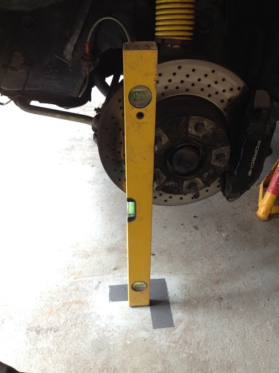
Before I took the stock suspension off, I put the car on stands and with the steering dead ahead and a vertical level marked up the position to the floor. This is obviously just to get the geometry about right, I can fine tune it afterwards. |
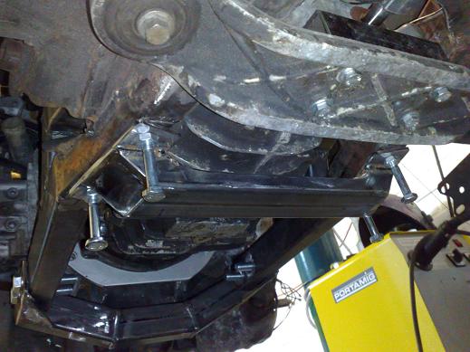
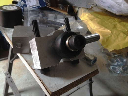
The key part to the swap is creating a forward bracket, this aluminium block spaces the anti-roll bar downwards with the stock saddle clamp and gives plenty of meat to mount the forward joint. |
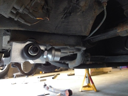
The block fitted, not how it is fitted to the chassis form. My mate, Seb, machined up some tube end fittings for it. |
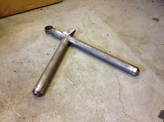
The first lateral link tacked together |
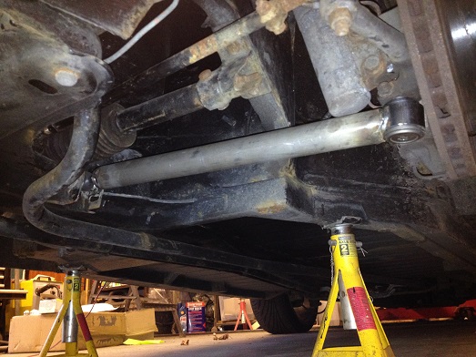
and fitted to the car, now to align the hub and measure up for the tension link. The last bit will be to work out how to connect the anti-roll bar. |
Tension link tacked in at nominal geometry position. Some people will fit a clevis type joint to the lateral part but I only wanted minimal adjustment. Welded will give better stiffness. |
I trawled ebay for a nice short anti-roll bar that I thought I could adapt and ended up with this from a Mk2 Ford Mondeo, less than £5 delivered for the pair! It was a case of making up some fairly simple adapters to bolt on to the standard 1303 anti-roll bar ends. |
Brackets to weld on to the new A arms |
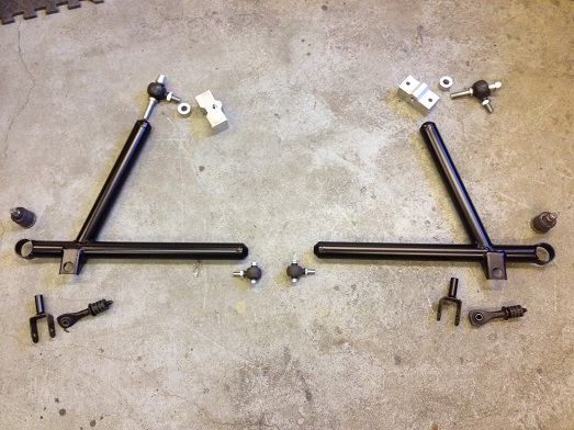
Finished A arm ready for paint |
Finished 'kit' ready to be fitted! Note I did machine down the blocks some more compared to earlier pictures to maintain the stock pick up position heights and maximise ground clearance. |
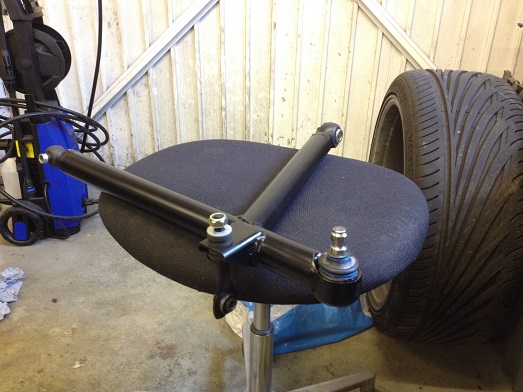
Ball joint pressed in and rod ends adjusted with their rubber boots to give them a bit more life |
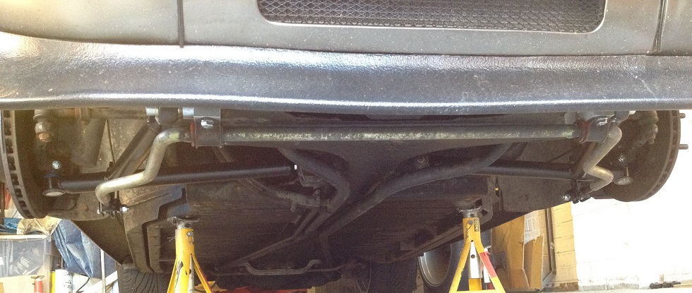
All done! |
|
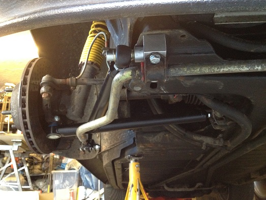
Closer view of one side.. |
So, the verdict: in summary well worth it! The front end feels so much more alive and communicative but NVH is hardly affected at all. The tyres seem to work a lot better as they are not moving around so much and the steering is even a bit lighter too. Even on motorways you can feel what's going on with the most subtle of movements. Overall it just gives so much more confidence in what the car i doing and that means a lot! For anybody else that wants to try something similar this is what I used: Inner joints: M10 male rod ends with high misalignment spacers Forward joints: M14 rod ends with standard misalignment spacer, additional 18mm spacer inboard Stock lower strut ball joints 1 1/2" diameter 0.1" wall thickness CDS tubing Mk 2 Ford Mondeo/Cougar rear anti-roll bar links If you can't work out the rest then frankly you probably shouldn't be trying to copy it!! |