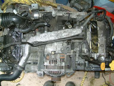
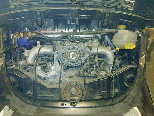
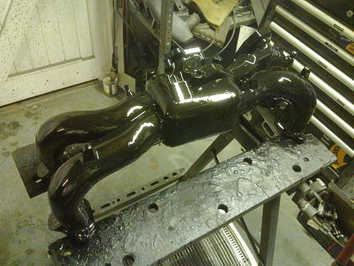
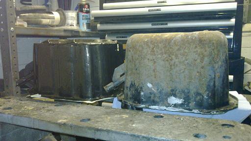
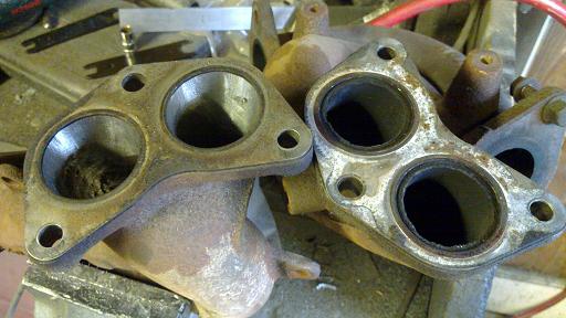
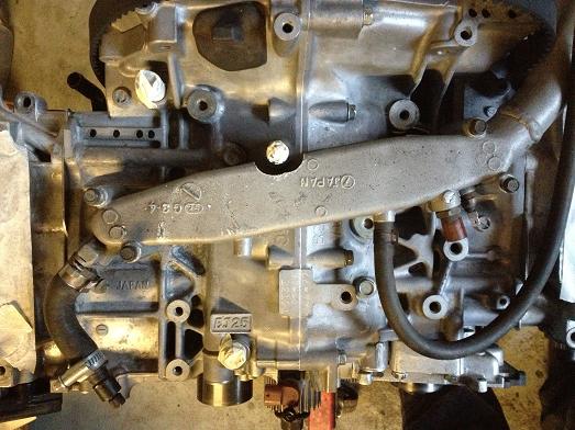
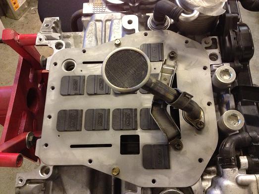
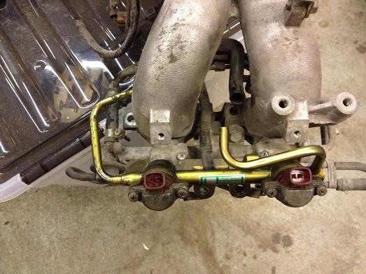
This is the stock coolant manifold on the turbo engine. On vanagon swaps it is common practice to reverse the manifold so that the coolant outlet points towards the front of the car. I liked this idea but haven't seen details of it being done for a turbo engine before so decided to have a go! |
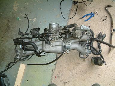
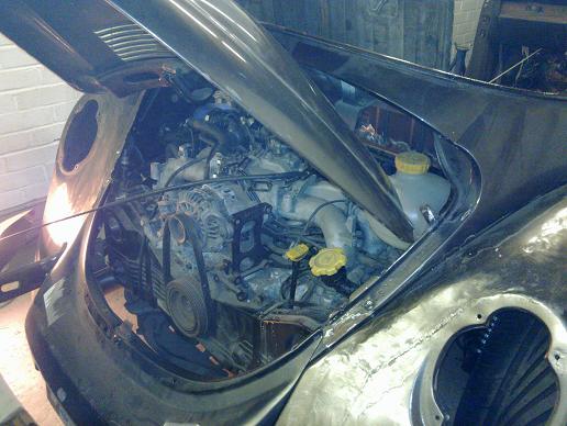
First step is to remove the intake which comes off quite neatly with all loom and fuel rail major parts. |
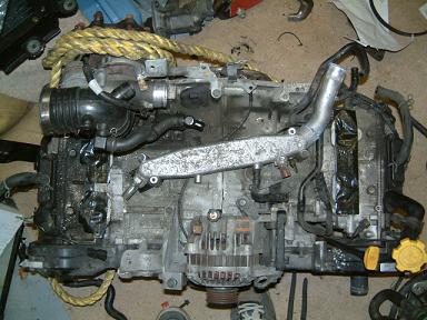
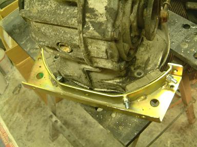
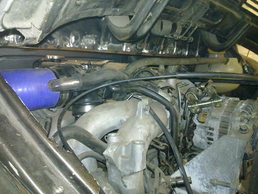
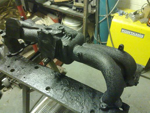
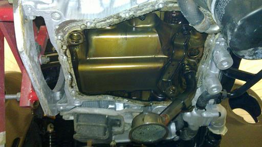
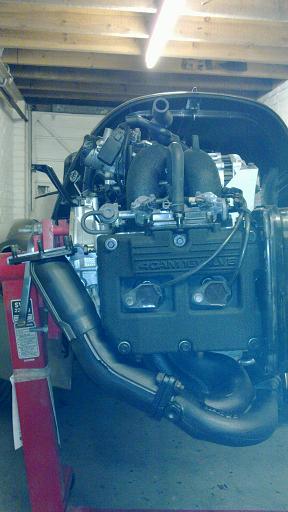
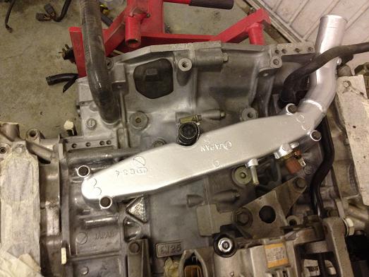
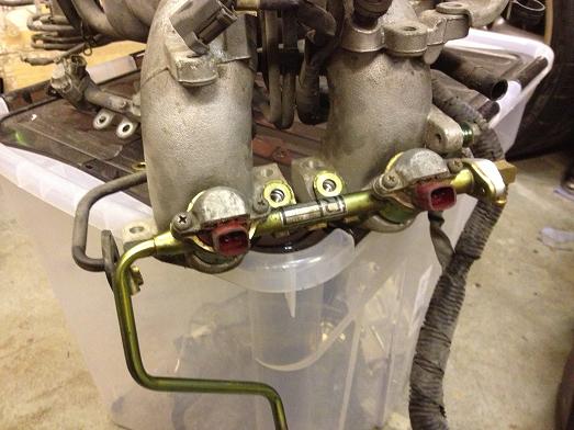
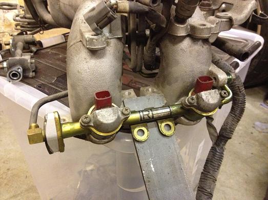
Here is the manifold reversed and the outlet pipe cut and repositioned so that it clears the crankcase and the intake manifold. The two temperature sensors will need the loom lengthened to reach the new positions, although I may get away with partially unwrapping the engine loom. The heater outlet will be blocked off and the heater will get its feed from the front of the main hot pipe at the front of the car which will save one long pipe. I will also use a larger header tank as the original is not big enough for the increased capacity. I will relocate the header tank and simplify the necessary pipework. Finally, the intake manifold has a coolant feed from the coolant manifold which will either have to be reversed or extended, you can just see it next to the temperature sensors. |
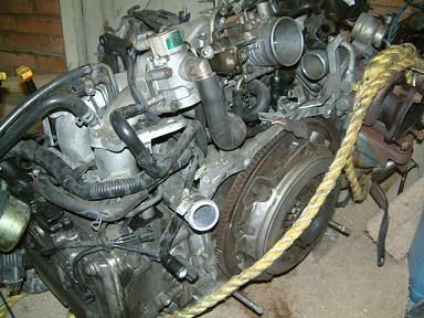
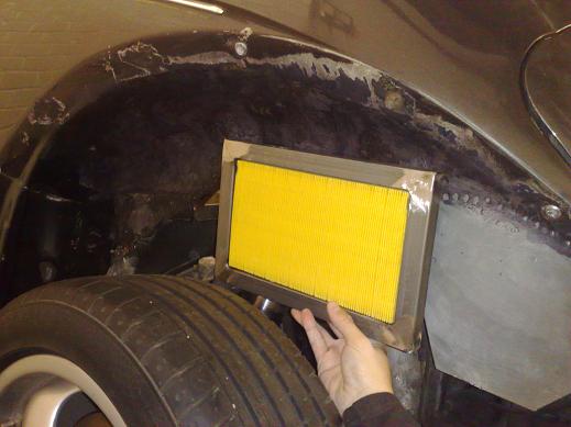
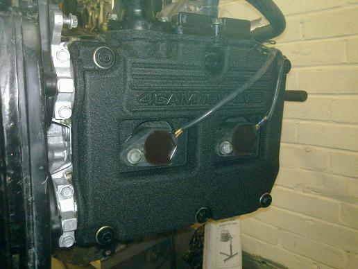
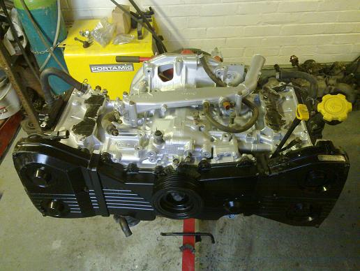
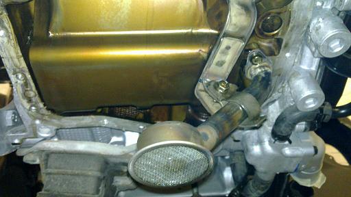
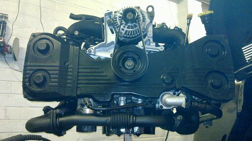
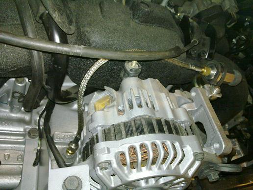
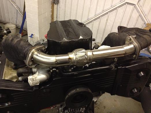
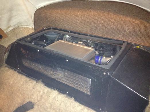
This is what it looks like with the manifold fitted. |
|
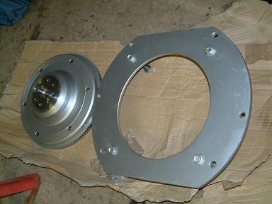
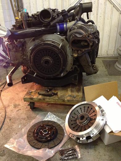
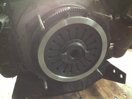
The engine adapter kit arrived from DS tuning |
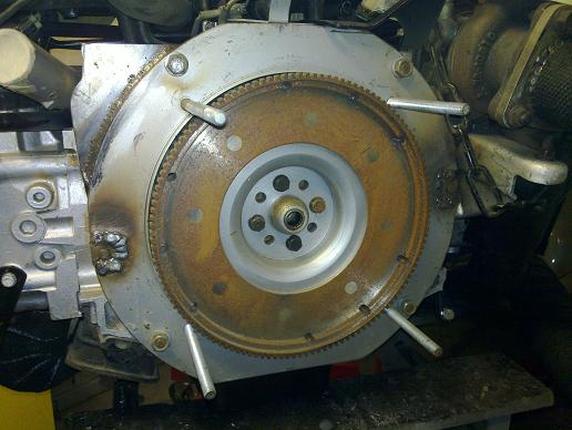
Steel plate with a flywheel for a 200mm VW clutch. |
|
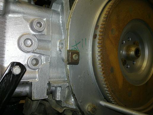
The bolt pattern for a VW and Porsche are the same up to the water-cooled generations so the adapter plate works fine. |
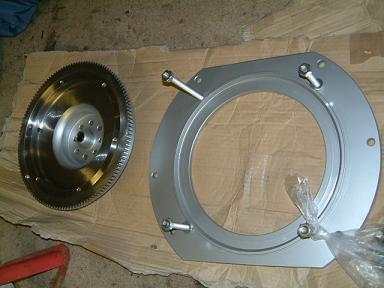
Just a small amount of clearancing for the turbo bracket required... |
I also need to replace the studs with longer bolts as the G50 is thicker than the VW trans, I need M10x130 and M10x150mm. |
with the chargecooler... |
|
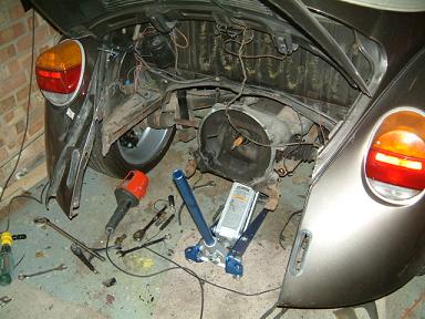
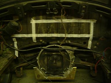
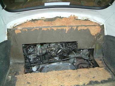
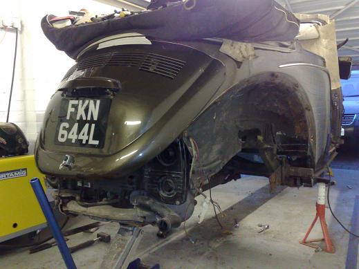
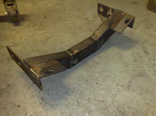
Rear of the car cut away, now I can measure accurately what needs to be cut from the bulkhead for the Subaru engine to fit. I'll order a new heavy duty rear mount, which will be reversed, and a mid mount. |
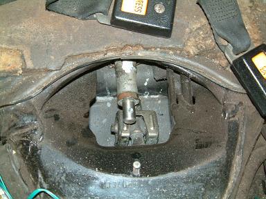
Berg style mid mount used as the front mount is not. |
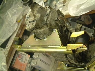
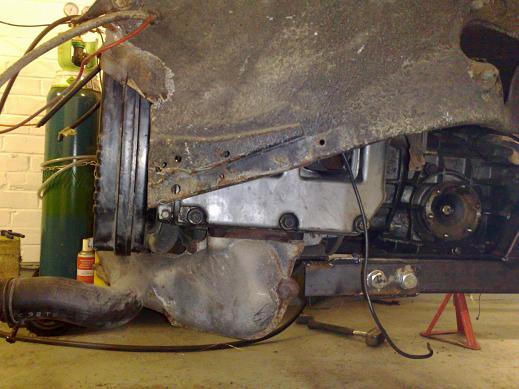
Heavy duty rear cradle and genuine VW rubbers. The cradle is reversed which results in the gearbox being moved forwards 46mm. |
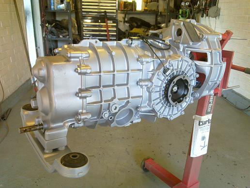
Here's the gearbox ready for installation |
The nosecone needed it's webbing clearanced to fit and clear the torsion bar housing. |
It's VERY tight in there! |
Using the input shaft as a datum, bulkhead marked for where it needs cutting for the chargecooler, pipework and turbo. |
Nearly there... |
|
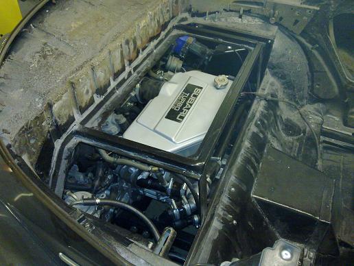
It's in! |
Cutting needed in the bulkhead |
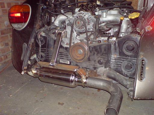
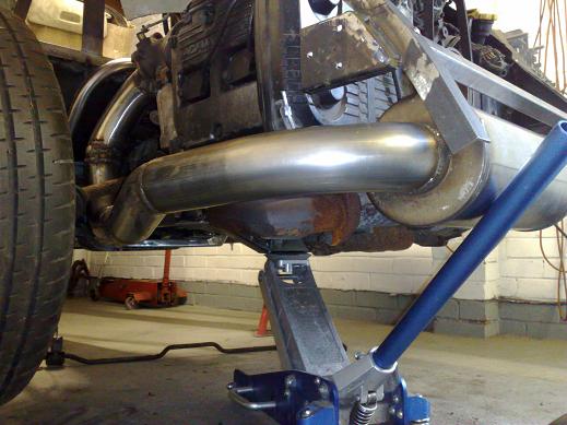
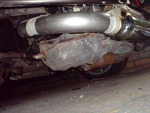
Quite a lot of space behind the engine, more than enough for the muffler |
Surprising amount of ground clearance, I may not even both with shortening the sump... |
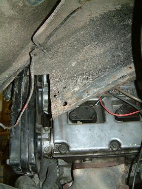
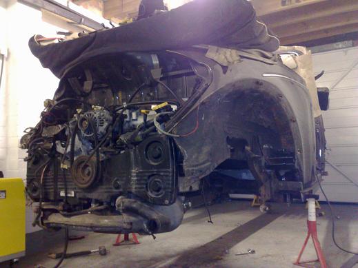
To give an idea of space under the wings to the cam covers, even moving the trans forwards it is still very close and I still need to do some more clearancing |
Lower fixing bolt which holds the adapter plate to the engine needs replacing with a countersunk one as it catches on the rear cradle |
You can see how far forwards the nosecone has moved. Shift rod needs shortening to match. |
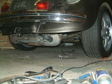
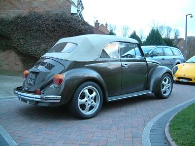
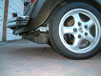
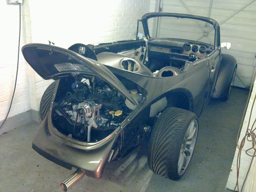
This is the ride height after fitting the engine, the top of the tyre is 1 1/2" from the wing |
with 5" ground clearance to the bottom of the sump, so if I lower it about an inch and shorten the sump 1 1/2" I'll have 5 1/2" ground clearance which is plenty! |
 |
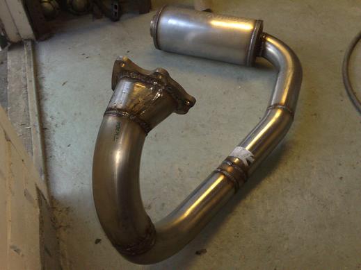
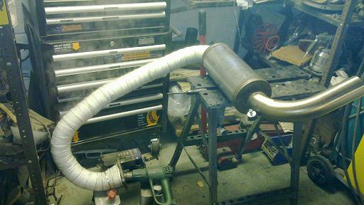
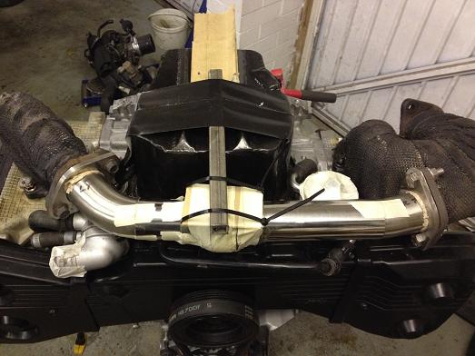
I've made up a bracket which comes off existing brackets on the engine that leaves the stainless muffler across the back of the engine. End fittings incorporate exhaust clamps welded on and everything will be easily removable. The tailpipe will exit from one of the standard cut-outs (to be shortened from above pic), at the other side the exhaust pipe loops up to the turbo flange. The muffler is reversible, one way for flow and one way for noise reduction. From the turbo back it is completely stainless. |
 |
First stab at an adapter kit from DS Tuning, I had to return it as the dowels didn't line up and the flywheel appears to be for a different year 911... |
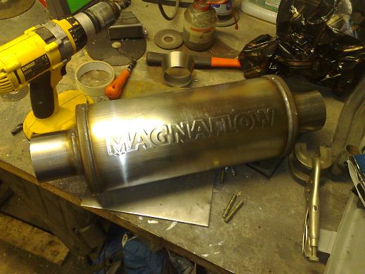
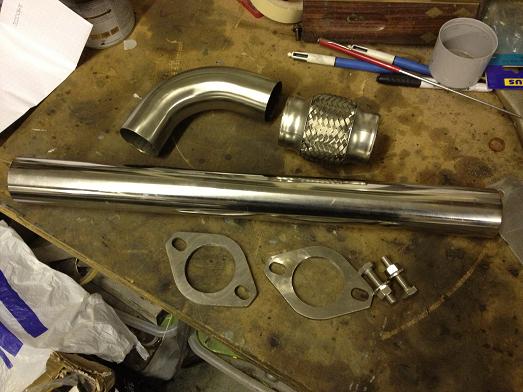
Found this stainless muffler at a kit car show, now I have more space behind the engine I want to make the most of it and quieten down the exhaust a bit. |
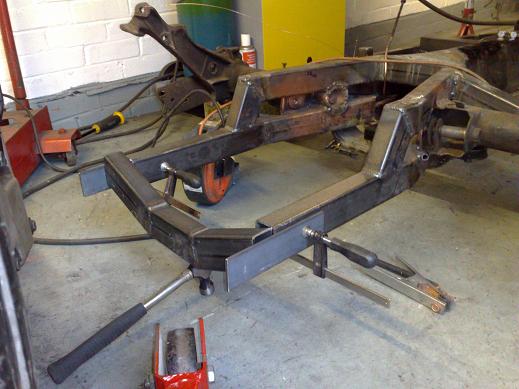
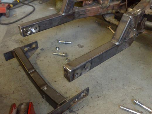
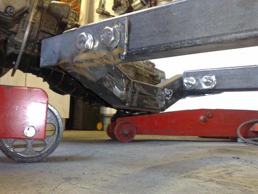
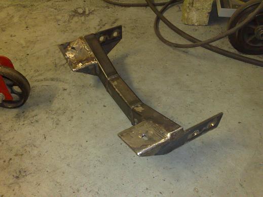
I decided to use some nice big bolts for each side of the engine cradle as it is slightly cantilevered off the end of the framehorns, 2 M16's on each side should be enough! Tubes welded in through the framehorn and also the ends capped off. |
|
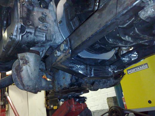
Here's the cradle in place, just have to get the engine and trans in the chassis with the body on and then I can finalise the position of the tab that goes on to the subaru engine mount... |
engine and trans hoisted into position and cradle offered up |
New trans tunnel required! |
Clearance to body is fine... |
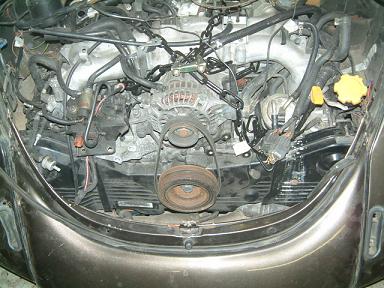
Engine in position on new mounts |
a bit more to do, I'll extend the bracket to fully support the subaru bushing and also improve the platform supports
|
 |
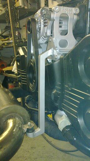
Finished engine mount cradle... |
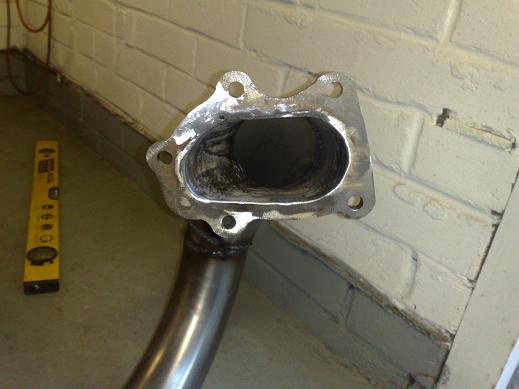
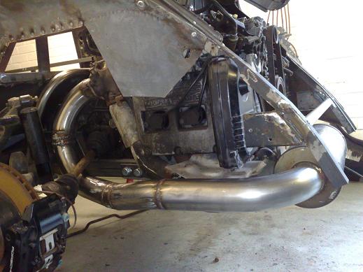
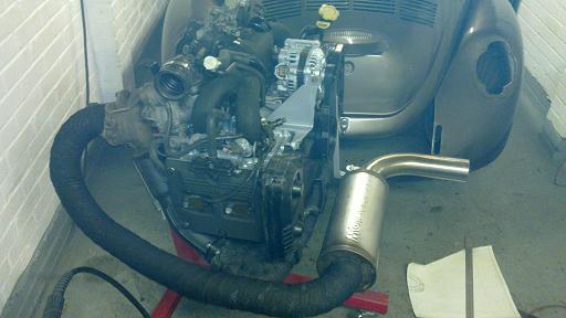
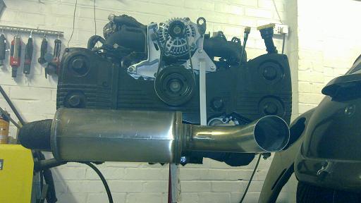
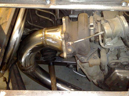
Here you can see how the entire turbo outlet transitions into a 3" system |
|
Just the tailpipe to weld on, it will exit in one of the stock positions. |
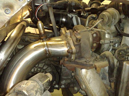
About an inch to the axle but this is at full wheel rebound and normal clearance will be much better. I am moving the oxygen sensor from the original position before the turbo to after the turbo to make way for the pipe alongside the engine, once I've bought a stainless fitting I'll weld it in... It will be also wrapped in thermal tape. |
 |
Just hangers to make and then weld on the tailpipe... |
Oxygen sensor boss also welded in, the original position in the manifold would have been vulnerable to damage and was in the way of where I wanted to run the main pipe by the head... |
|
Header tank is from a Vauxhall Corsa/Tigra as it had the right connections. I didn't like the subaru system as it is based on an external overflow tank. An aftermarket one would have been solid aluminium so levels are not so easy to check. I welded on a couple of brackets to the body to support the standard fitting points on the tank |
|
Fill point is accessible when the decklid is open. |
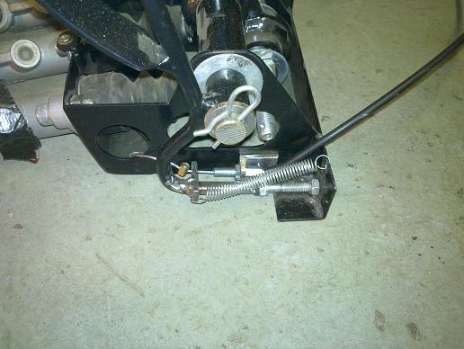
The OBP pedal box had no provision for the throttle cable so this is what I came up with. I also made up the cable from a universal kit using the subaru fittings/adjuster on the engine end. It feeds through the standard tube in the chassis tunnel. |
|
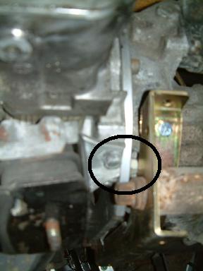
The G50 was a real pain to detail! Porsche use a really thick type of wax and liberally spray it on all over the underside. A 10mm wire brush was the best thing to get it out in the end. Lots of degreasers and finally etched and painted in alloy wheel silver should keep it looking much better and cleaner in the long run... You can also see the steel spacer under the front mount. |
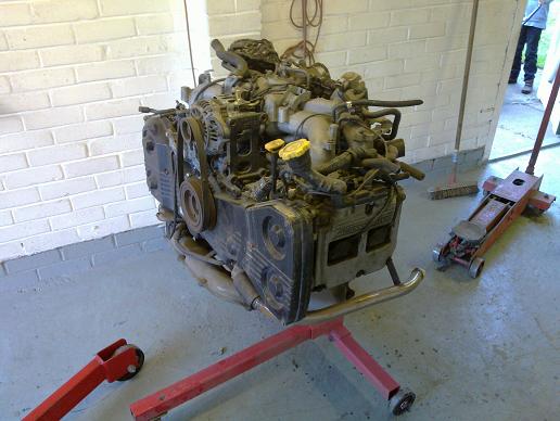
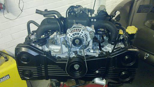
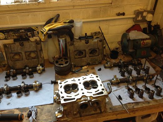
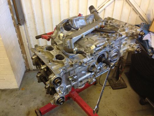
The engine's turn on the stand for some detailing... I'm probably going to go with black wrinkle paint for the alloy bits (cam covers and intake manifold). |
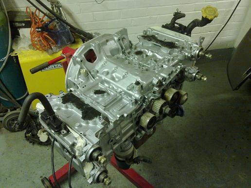
Stripped back to a bare long block and painted in POR engine enamel.. |
Cam covers were stripped back and treated to some VHT black wrinkle paint. |
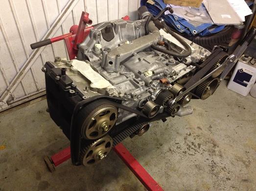
Coming back together, new cambelt hiding under there too... |
Lots of now redundant bosses were cut off and smoothed to give a cleaner look and the manifold also painted in wrinkle. This is how it looks straight away... |
....and after a couple of hours! |
Engine just about ready to go back in the car... |
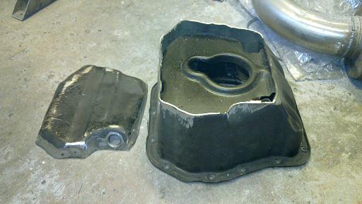
I decided to shorten the sump but only by an inch or so as that will just about bring it level with the exhaust manifold and oil filter and maximise ground clearance |
Cut up and new component parts. I filled in the slope at the front part to regain lost capacity and it turned out near enough identical to the original volume. I cut slots at the top and bottom of the additional triangular section so the old sloped wall acts like a baffle. |
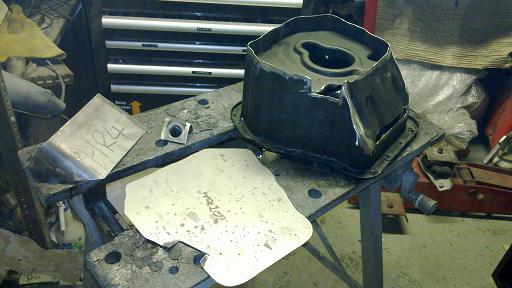
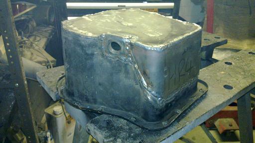
All welded up, just needs a clean and like of paint, then to shorten the pick-up tube. Note the drain plug is at the low point... |
In the end I welded on some strengthening ribs which also serve as a flat bottom and stop the drain point getting damaged. Note that the old sump drain 'bulge' has already been flattened on the old sump so the gain is better than it looks here... |
Stock pick-up pipe |
shortened to suit the new sump. I also had to shorten the support piece. Normal clearance to the bottom is 16mm but I reduced this to both gain useful capacity and it was easier to just shorten the vertical section and braze it back together, I ended up with 9mm to the bottom. Apparently subaru rally cars are modified to only 6mm... |
Finally fitted, the actual oil part of the sump is level with the bottom of the oil filter and I didn't want that to be the lowest point. All in I have gained about an inch ground clearance. |
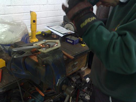
While the header was off and in pieces I took the opportunity to get the die grinder out and do some match porting, apparently this is good for up to 30bhp! |
All painted in high temp paint and mocked up on the engine to check ground clearance. The aim was to make sure the oil filter wasn't going to be the lowest point and this looks about right to me... |
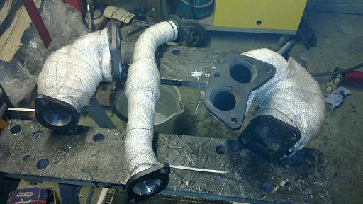
The original up-pipe lagging was savable so just painted but the rest will be wrapped and repainted. |
Manifolds wrapped. I used the stainless ties that came with the wrap but found stainless MIG wire worked better, fitted every few inches. |
8m of 2" wrap went into the manifold and another 10m for the downpipe! The wrap was soaked in water first as it later shrinks to a tighter fit as it dries out. Due to the low temperatures at the moment it was taking forever to dry out so I improvised and left the hot air gun blowing down the inside of the exhaust and it worked great! |
Additional support made up to support the muffler end of the exhaust. I managed to scrounge enough stainless bar to make a bracket on the exhaust and made up the support using a mini style exhaust rubber mount. |
All fitted up. Note I also painted the wrap to stop it absorbing water, oil etc later on.. |
Quick check to confirm the muffler is not the lowest part.. |
A while back I realised that the dowel alignment holes in the adapter plate were machined incorrectly and the supplier refused to fix it so I either had to buy a new one or sort it out myself! Previously I had filed out the holes to get the adapter plate to bolt on but it was not concentric to the crank centerline. I decided to cut the old holes out, then weld in new thick sections in the correct place. Here's one of the new sections before cutting into the plate. |
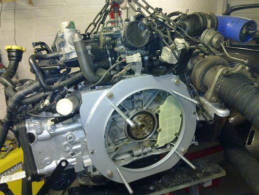
There are two alignment holes, one on each side, so I turned up the MIG and welded the new sections after making sure the plate was aligned correctly, this was done by using a depth gauge all around the trans locating ring up to the flywheel diameter and repeatedly tweaking things until it was all perfectly aligned. While I was at it, I also welded on a small plate on the upper left corner to cover up an opening. |
All cleaned up and repainted before fitting the nice and clean engine! |
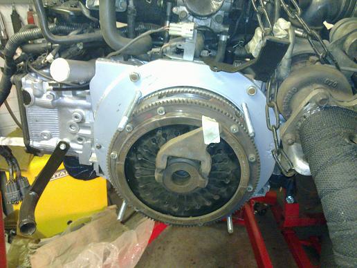
Stock 911 clutch all fitted up, the release arm needs to be attached to the release bearing before you mate the engine and trans, the pivot bar is then slid through it's centre through bosses in the bellhousing. |
All together again for the last time before it goes into the car! I also made up a new clutch hose to mate to the slave cylinder. |
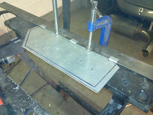
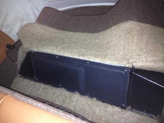
Making up an access panel for the offside rear inner wheel arch |
|
Engine and trans in! You cna also see the inspection panel in place.. |
I welded up an adapter for the clutch slave pipe. It was an M14x1.50 thread and 8mm pipe which I thought was very big, I've decided to use normal brake pipe size so had to adapt down to M10x1.0 and used a spare brake flexi pipe I had.. It is all kinked over a bit to get extra clearance to the exhaust downpipe. If it turns out to be too restrictive I can easily go up a size later on. |
A hell of a lot of pipework has been completed and the chargecooler repainted and fitted. |
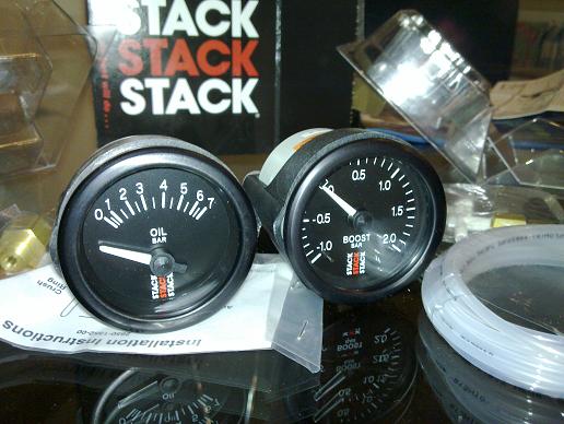
I thought it would be a good idea to better monitor the engine so got a couple of stack gauges, due to their reputed accuracey. |
The oil pressure sender required a T piece to keep the stock pressure switch, as there isn't enough room under the alternator this short extension places them both remotely. |
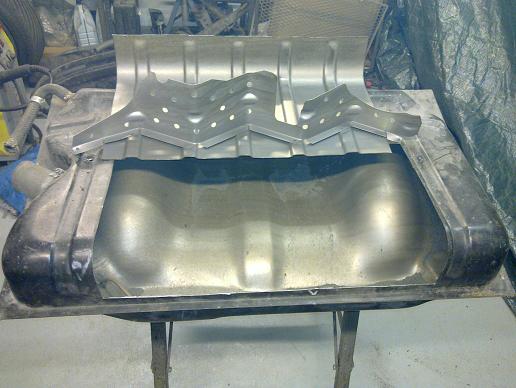
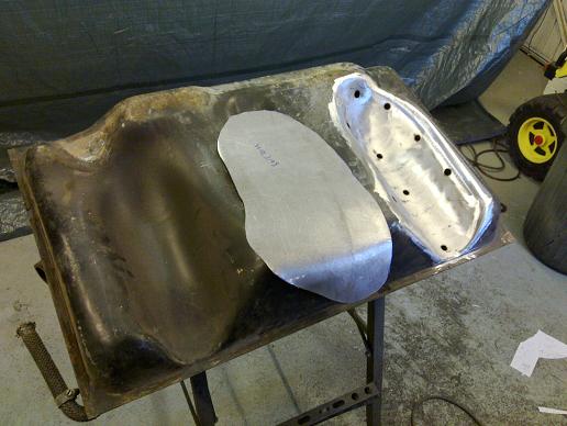
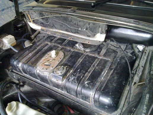
Time to modify the stock fuel tank for fuel injection, I was surprise to see that the stock tank incorporates a baffle across it. |
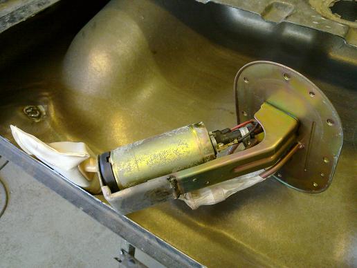
The tank is shallower than the subaru one so I shortened the subaru fuel pump mounting assembly and removed the stock level sender. |
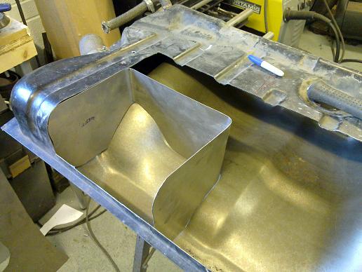
I made up a baffle to hold fuel around the pump as the last thing you want is to lose fuel pressure on boost in a turbo engine! I drilled some holes through the plates to allow fuel to flow through it. |
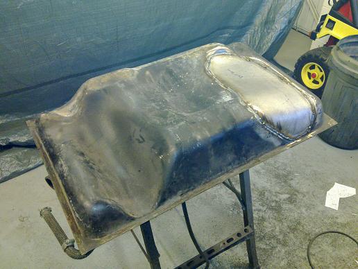
I also increased the fuel tank volume by filling in the LHD steering column recess. I left the metalwork in place so it acts like a baffled volume. |
Underside done! |
Topside done! I welded up the stock level sender hole and made up a new one for the Porsche dip tube type to match my gauges. The fuel pump section from the subaru tank was welded in to the top of the tank. |
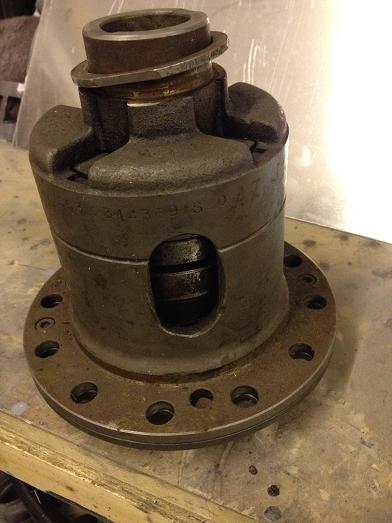
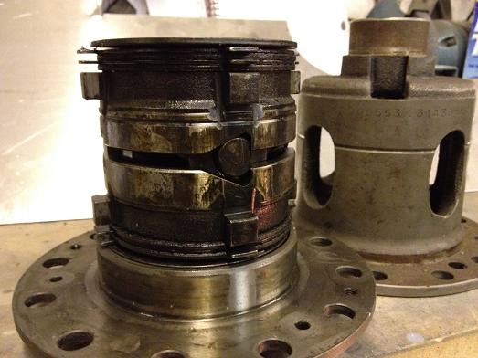
LSD as received with the gearbox when I bought it, bit of an unknown quantity! |
Opening it up the ramps show it is out of a 964 RS/turbo which means 20% lock on acceleration and 100% lock on overun. This has really helped the car fee much more predictable and also stable, especially after the suspension unloads after hard acceleration. |
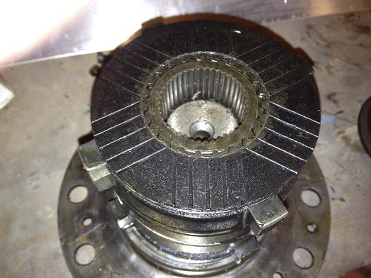
The friction discs proved to be in as new condition, result! I was going to have a go at fitting it myself but was unable to measure everything accurately enough. The trans had different brands of bearing either side of the differential so during the swap I had to replace: bearings, ring gear bolts (longer on LSDs), seals, oil, shims. With labour that lot added up to £580!!! |
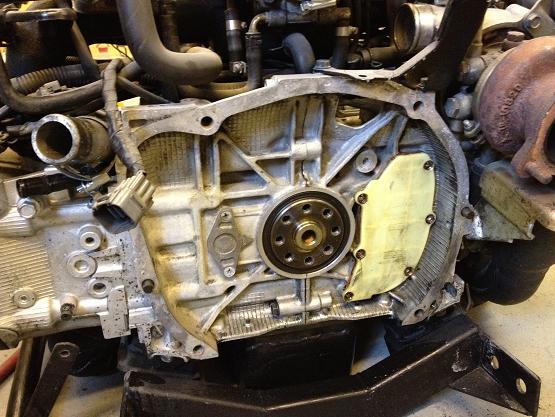
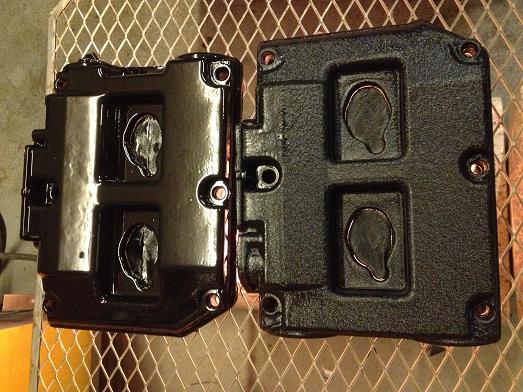
The main reason for taking the engine out (other than boredom waiting for the trimmer), was to sort out a minor oil leak coming from behind the engine, a very common fault with subarus. |
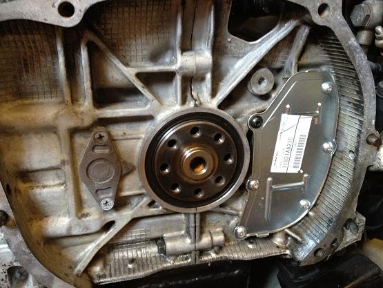
Here's the updated subaru part, steel plate and new screws fitted with a sealant. The black screw is supplied with dry loctite on it, forgot to look why, probably as it was a through hole so needed sealing? |
|
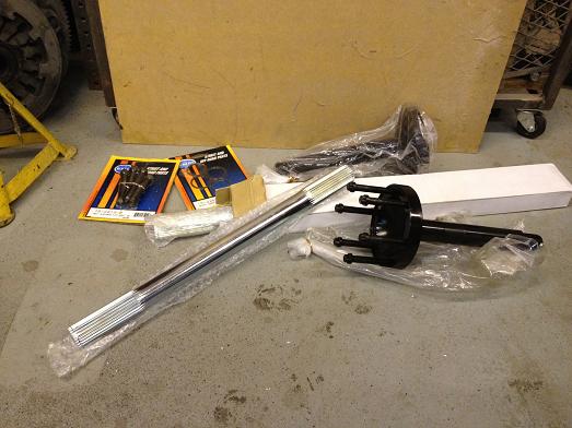
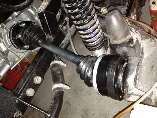
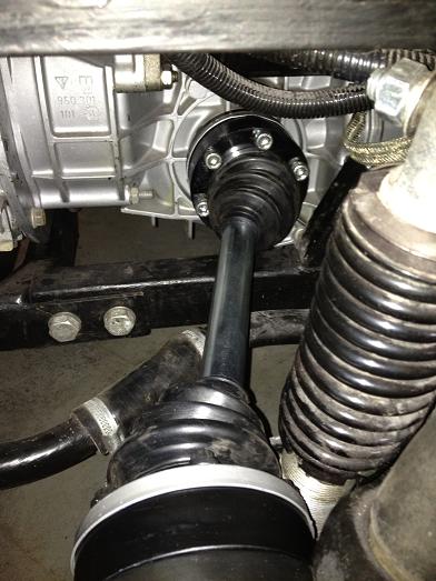
The old 944 CVs were clicking a bti and my plan was to upgrade to 930 CVs anyway. Here are the bits needed for conversion; new stub axles, I already had G50 trasn drive-flanges, custom length axles (16 1/4") in 28 spline to match the CVs. |
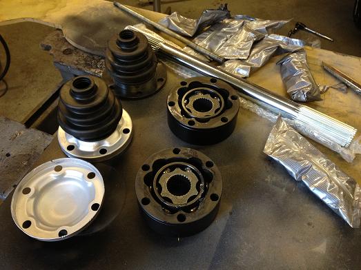
Here are the GKN CVs, I cleaned up the flanges that came with my gearbox but needed an extra pair. After getting up off the floor after being quoted £120 each from Porsche I found some cheaper options from prolinx. |
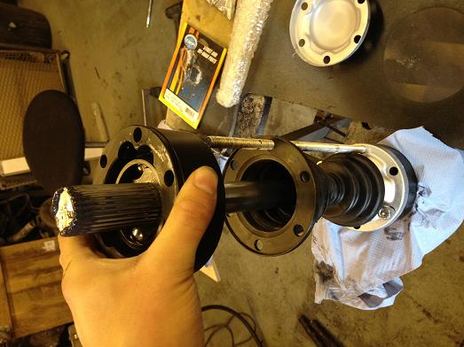
CVs are being 'clocked' as this gives them the best alignment relative to each other, just like you do with a UJ. |
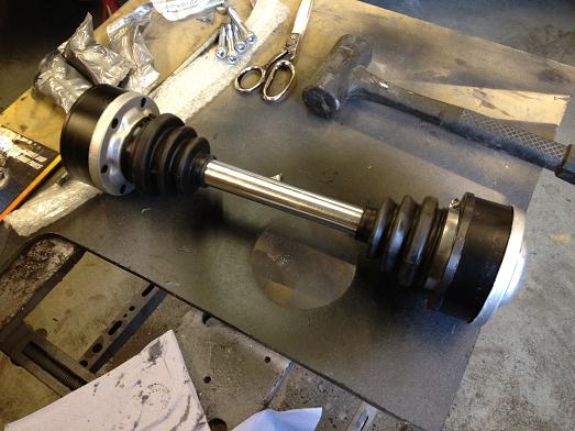
All ready to go on the car |
And fitted! |
Clearance is very tight to the coil-over but is passable (this is worst case compression clearance). I spent ages trying to get some smaller motorsport CV boots from GKN only to find that they had stopped making the size I needed! |
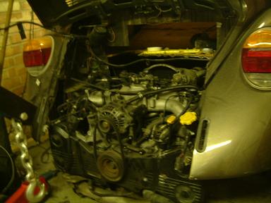
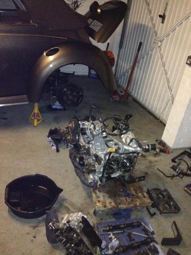
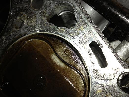
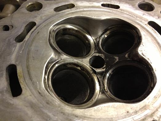
Engine out again.. It was blowing a LOT of oil and no power so I did a compression check to reveal that one clinder had absolutely no pressure. |
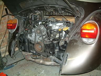
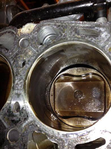
You can just about make out some damage to the top of the cylinder wall |
and if you look carefully you can see that the ring is distorted, I'm assuming that the piston ring land has failed underneath... |
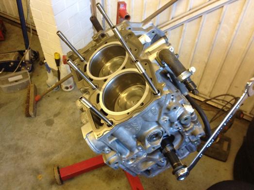
With that block unusable in its state I decided to bring the final plan forwards... So, with a bit of hunting I found a 'rebuilt' 2.5l STI shortblock on ebay. Final build will consist of 2.5 sti upgraded with forged pistons, V3/V4 sti heads which I will rebuild, upgrade one of my turbos to td05-20g, new bigger injectors, new oil modine, sump baffle plate and probably some other supporting mods being topped off with a remap on an ESL daughterboard, probably by Bob Rawle when he visits API. |
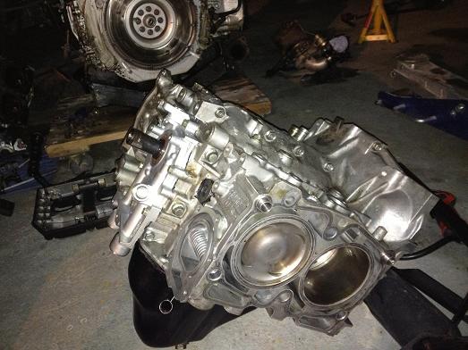
The shortblock as I received it. With some thought I decided that I will always feel uneasy about the stock pistons as they haven't got a very good reputation. After a chat with David at API (well respeced Impreza engine builders only 5 miles away from my house!) I decided to go with some forged pistons. Supertechs have a good reputation for not being rattly like most and API have experience of them so that's the way I have gone. The stock rods are good for 450bhp ish as they are the latest spec ones. My goal is a good 400bhp. |
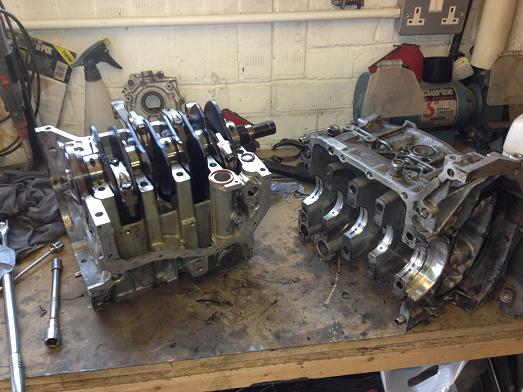
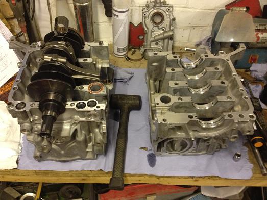
Time to split the block as the cylinders needed honing to fit the pistons. It would also give me a good opportunity to inspect the 'rebuild'. |
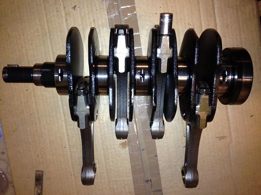
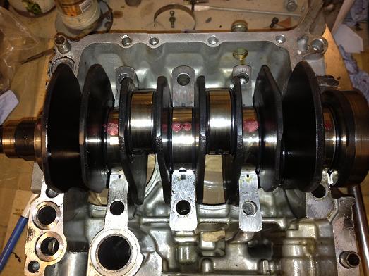
Crank and rods out... |
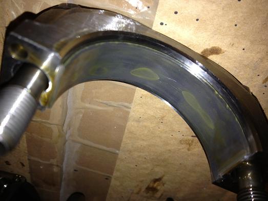
The big end bearings were supposedly new! I've replaced them with ACL bearings |
Main bearing clearances checked with plastigage, they are all good, as are the bearings. Luckily this is the better nitrided crank too.. |
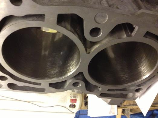
Block halves back from API after being honed, they have been done to 3.8thou piston clearance. |
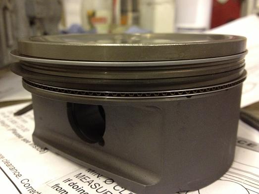
Here's the first supertech piston, I've gapped the rings to specs.. |
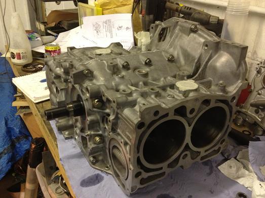
Block ready to go back together with new seals, note tape on rod little ends to avoid the risk of scratching the bores on assembly. |
All torqued and sealed up.. |
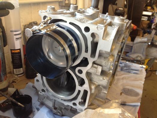
first piston going in... |
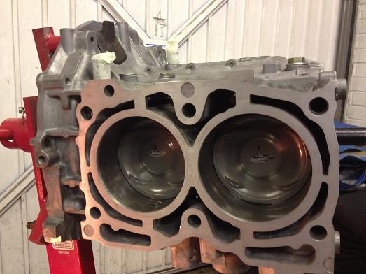
all pistons in, you have to make sure they are all orientated correctly as well as positioning the piston ring gaps too |
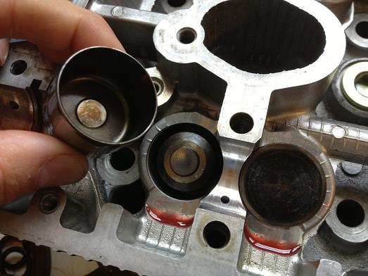
V4 STI cylinder heads stripped for refresh. All valves cleaned up, re-lapped in to the heads and then ready for first lash measurement. These heads use under-bucket solid shims which come in various different thicknesses and you change shims to get the correct clearances. |
I knocked off any sharp edges in the combustion chamber to help avoid detonation, this can sometimes be an issue when fitting 2l heads on a 2.5 block due to the slight cylinder diameter mismatch |
You can see one of the shims sitting on top of a valve. |
Lots of measuring! |
and measuring, then swapping shims |
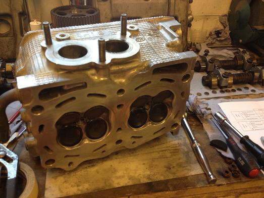
Ready to go on the engine! |
ARP head studs fitted to give better head gasket clamping under boost |
Back to a longblock! I had to fit the cambelt and re-check the valve clearances as the cam loading can change things. Luckily only one shim needed swapping after assembly. |
V3/4 cam covers were cleaned up and treated to some VHT wrinkle paint, note one on left hadn't had any heat applied ot get the wrinkle effect started yet. |
Coolant manifold needs modifying to clear the central 2.5l breather pipe. |
 |
As it was apart, I've gone with an RCM oil baffle plate to help avoid surge. |
Coolant manifold TIG'd back together, I deleted the normal heater pipe as I found as it's new role as a manual bleed I never actually got any air out of it and this way I have more space if I decide to go with a direct turbo intake under the intake manifold |
Parts to make up a large bore exhaust crosspipe. I had already ported the stock item but it was still very restrictive. Grimmspeed sell one but I thought I may as well make one myself |
I held the flexible section in mid air and then joined the dots with pipe. |
tacked together and now ready for finish welding. |
Bought a set of 740cc/min Nismo phase 2 injectors, the phase 2 fuel rail can apparently be fettled to fit the phase 1 so I prefer this to using adapter rings. Note mounting tabs are on the wrong side of the rail |
if I flip it around then the pipes are completely wrong |
Might make an adapter out of a piece of 5mm plate like this... |
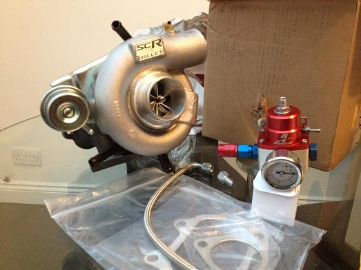
Shiney go-faster bits have arrived! Scooby Clinic SC46 billet turbo based on a Garrett ball bearing core, good for 460bhp on V-power and an Aeromotive fuel pressure regulator to go with an uprated fuel pump and parallel fuel rail conversion. |
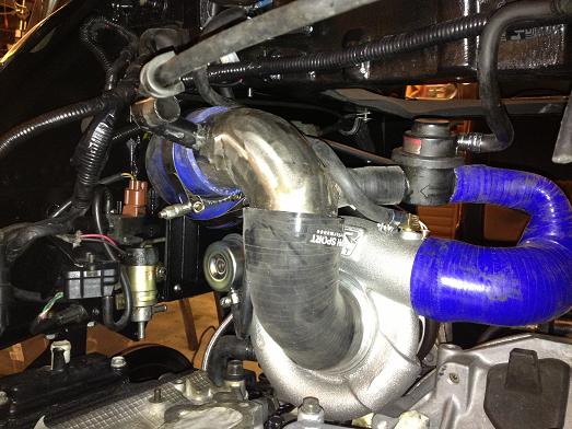
I've had to make a new intake to suit the front entry turbo, I could have gone under the inlet manifold but it would have lengthened the intake by a fair bit. |
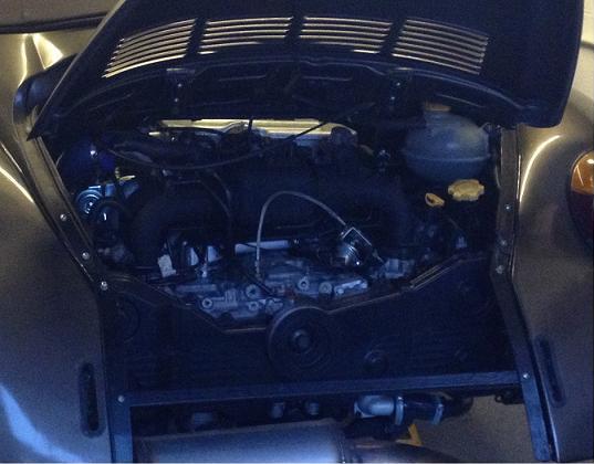
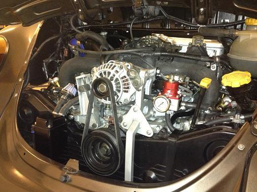
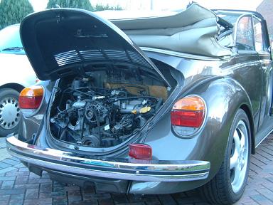
Engine back in the car and fired up for the first time, it sounds good! |
More bits arriving are: oil breather catch tank inlet manifold thermal insulating spacers HRC 310 lpm fuel pump |
Oil breather tank hanging off the back, there wasn't much space anywhere else! I also made up a new bracket which supports both the oil pressure senders and the Aeromotive fuel pressure regulator |
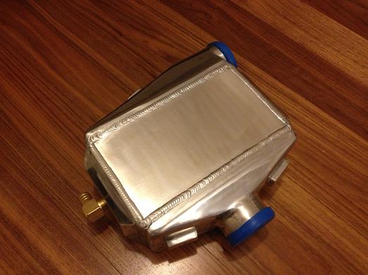
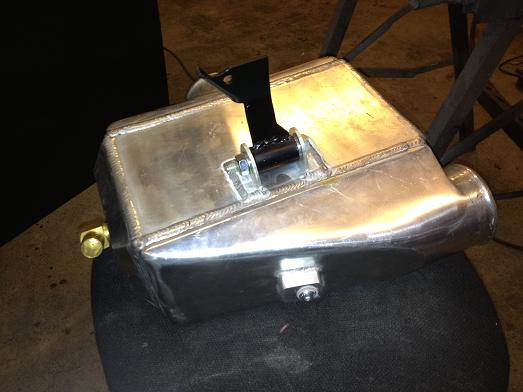
I was advised by my mapper that the old Legacy chargecooler would be limiting my performance so it was time to upgrade. I considered an air/air using enlarged ducts built into the rear wings but I don't really think I've got space for it. I eventually found a very good thread on using a frozenboost type 14 chargecooler. It is apparently good for 700 CFM / 600 BHP and one person reported that when running 22psi he sees a maximum of 10 degrees above ambiant but normally only about 5 degrees which is pretty efficient in my book! 2 weeks later and this arrived in the post:
|
I wasn't satisfied that the system would be wirking well without trapping air so I decided to drill and tap a bleed point. I drilled on a tilted table on my pillar drill very cautiously as I didn't want to wreck the core! Turns out the end tank isn't completely solid as it looks but cast and it hollowed out a bit with extra clearance to the air core so wasn't too bad to do. A small M6 bolt with O-ring will serve as a manual bleed.
|
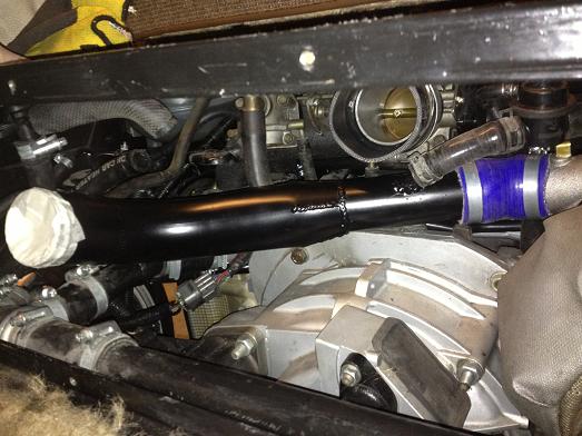
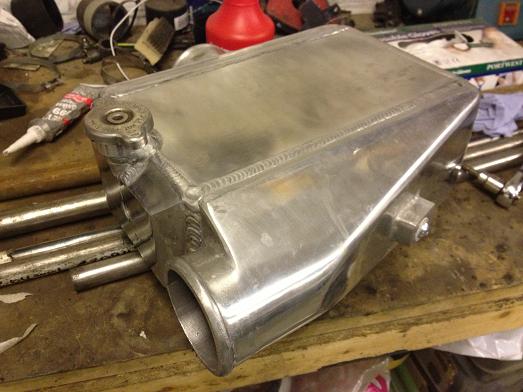
The turbo pipe I made up to join to the chargecooler inlet. 2" going up to 2 1/2" with a fitting for the reciculating dump valve. I had off-cuts of stainless lying around from old exhaust system build so I'm sure it will do the job fine. The 2 1/2" end joins to the chargecooler with a 3" to 2 1/2" silicone reducer elbow.
|
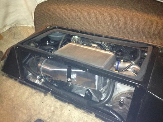
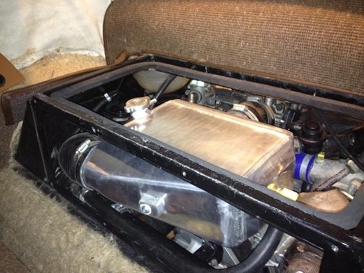
You can see a strap supporting the weight of the chargecooler off the frame above via some rubber washers to isolate it. Just in sight is a filler cap from a Suzuki motorbike which has the correct size fittings for the water pipes. |
Finally I had to some some re-shaping of the bulkead panel to clear the end tank. |
I made up a new bulkhead panel to properly clear the new chargecooler. |
New stage 1 KEP clutch, this is rated to 550ft lbs torque so fine for my target level of about 450.. |
 |
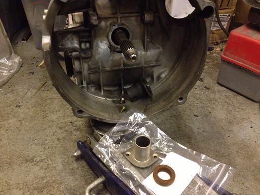
The release bearings changed to include a plastic liner, this meant that I needed to buy a new bearing guide tube from Porsche.. |
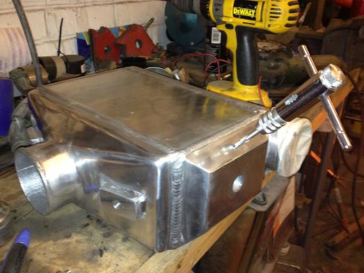
While the chargecooler was off again I thought I would take the opportunity to improve the mounting and filling system. Here is a new support bracket using a locost type suspension rubber bushing I had lying around |
New filler neck welded to the chargecooler makes the pipework much neater and is obviously much easier to bleed and keep full. The filler neck was decent and came from Mishimoto, most others were pretty flimsy pressed items. |
All fitted again, the chargecooler is much better mounted and easier to fill now. |
|