Design of the wishbone front end...
After thinking about doing this for far too long I thought it was about time I did something about it!
Looking at the basic setup of the VW suspension, which has zero camber changes in roll, I decided to do something about it using the tried and tested system of unequal length wishbones. As I intend to offer it for sale, once proven, it needed to be a bolt on setup which included a suitable steering rack. The A arms will use standard high spec German press-in ball joints.
In the future I may even develop an active anti roll system! I have worked on VM systems in my Mechanical Engineering career so far so I know the theory for the control and mechanical application
|
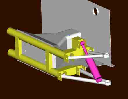
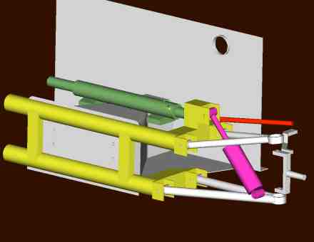
First I modelled the front end using Pro Engineer (I use this package a lot at work), this gives me a pretty good idea of what can be done as long as it is all done accurately. The frame uses the centre part of the original beam, with 50mm square, 3mm thick box section tubing for the rest. Some final strengthening tubes will be added once steering clearances are known better. |
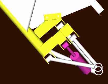
This view shows the different wishbone lengths and the built in caster. Both wishbones will have adjustment by using shim washers either side of the bushes. |
|
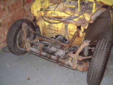
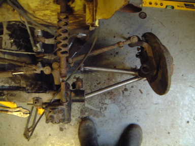
What I started with! It seemed a shame to miss out on this opportunity while the front end was not yet fitted to the Ghia. A stock ball joint torsion beam front end with discs. |
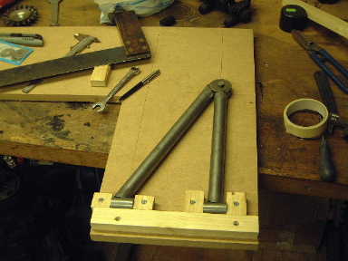
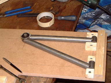
This is the jig I made for the lower wishbone, it holds the bush tubes in position as well as the ball joint ring and then the tubes are cut to length and fish-eyed to mate nicely together prior to welding. |
|
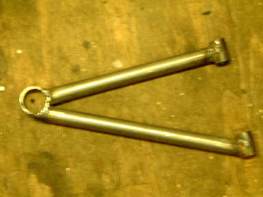
All the tubing is standard size CDS for strength, apart from the thick wall ERW for the ball joint which was chosen for size (press fit). |
Here is a welded up lower arm. My digital camera has been playing up which is why it is out of focus! |
|
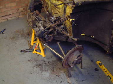
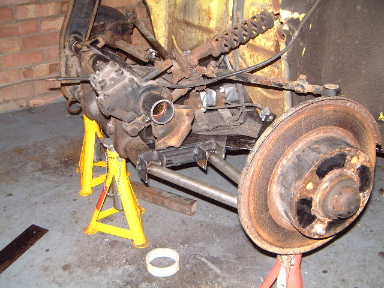
I first removed the torsion leaves before cutting the upper and lower tubes down. To keep a reference I welded the trailing arms of the opposite side in position so that I could make sure everything was set up symmetrically. |
Mocking the arm into position to give me an idea of the dimensions for the support framework necessary for the 2 arms and the coil-over damper unit. |
|
|
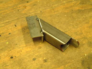
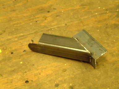
Now to make up some framework for the lower wishbone pivot points! |
|
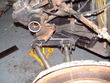
This will be welded onto the end of the lower torsion beam tube, the L-section sits on top of the chassis, holes will be drilled through and then bolted down. |
And here it is mocked up... |
|
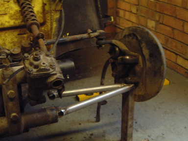
Everything fits nicely. The wishbone has its bushes and the ball joint pressed in here. I have intentionally made the brackets oversize to allow for some adjustment. |
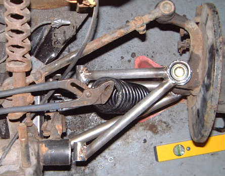
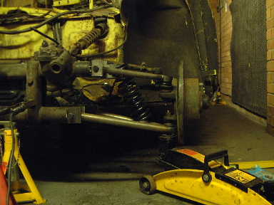
This is a spring suitable for a 1.9" damper unit. I am mocking it up in position to make sure I will have enough clearance. The aim is to get it as vertical as possible and for the lower pivot to be as close to the hub as possible to reduce stresses on the lower arm. The closer you get to a 1:1 ratio between wheel movement and hub movement the more adjustability you will have for the final setup. |
|
I went out and bought some new tools this week which should speed things up. A bench grinder and a pillar drill with circuler cutter to fishmouth the wishbone tubing properly for better and easier fits!
Plan view showing the spring clearances, it will be tight but very do-able. Another bonus of this wishbone set-up is that steering lock will actually be increased on my speedster as the inner wings aren't ever a problem. |
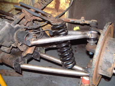
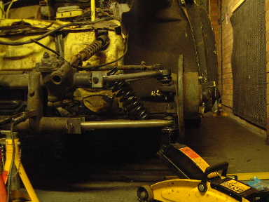
Here you can see that I have made an upper wishbone and half-pressed the ball joint in. I still want to tidy it up a bit so the ball joints will both be removed before the parts are prepped and painted once the damper position and brackets are finalised. Anyway, it's all looking good so far! I will have to cut off the steering lock bracket to get the upper framework in place, although I may be able to refit it to the new tubing if I'm lucky. I also will make the brackets for the upper wishbone bushes. These will bolt onto the upper framework so that shims can be placed inbetween themselves and the rame for big changes in camber, depending on ride height. |
|
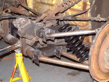
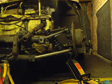
New top frame tacked in position! |
Full rebound |
|
Ride height |
and full compression. I am going ot measure the bump steer and then will make a decision wether to go for rack and pinion or not. |
|
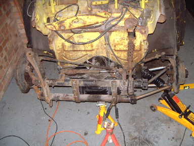
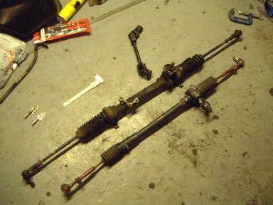
New and old together. |
I have chosen a rack to use which is easily available and good quality. It was chosen for its width between tie rod inner pivot points. The tie rods are too long, they will need shortening about 100mm each side. This will be done properly, the tie rods are solid so will just need cutting down and re-threading, as luck would have it the ball joints are also perfect for the VW spindle! As a comparison, the lower rack is one I have borrowed which is already modified for VW use. |
|
Lots of work has gone into positioning and selection of the steering rack to give good performance in respect of bumpsteer and ackermann steering... |

PLEASE NOT THAT THIS DEVELOPMENT IS ON INDEFINITE HOLD DUE TO OTHER PROJECTS AND ME NOT HAVING A TORSION BAR VW AT THE MOMENT FOR DEVELOPMENT